


Thanks for your thoughts on the MR-1 and how it gets away with cutting steel. Doing super-slow baby cuts in steel isn’t really a problem for the home gamer if it means being able to make a part as versus not being able to make a part.Originally Posted by peteeng

My mill uses 5M HTD pulleys and belt. The motor pulley is 63 teeth (94.7mm flange OD and 24.6mm inside flange width) and the spindle pulley is 38 teeth (64mm flange OD and 17.5mm inside flange width) with a 17mm wide HTD belt. The servo motor is 3000 rpm and 1.2kW.
I was told by Novakon that the spindle pulley couldn’t get any smaller because “the power of the servo motor is significant and to properly transfer the motor torque to the smaller pulley, the diameter and the number of teeth engaging the belt drive is a factor. There is not much room to enlarge the motor pulley and the size of the smaller spindle pulley can’t be reduced for practical reasons. To make the ratio any larger would also limit the maximum size that can be tapped due to loss of available torque delivered to the spindle”.
I would happily trade away some rigid tapping capability for increased rpm.
Results 61 to 80 of 160
-
03-14-2023, 08:04 AM #61
 Registered
- Join Date
- Oct 2009
- Posts
- 482
Re: Gantry 3-axis milling machine Design preparation phase
-
03-14-2023, 08:53 AM #62
Member
- Join Date
- Jul 2018
- Posts
- 6318
Re: Gantry 3-axis milling machine Design preparation phase
Hi TiBoy - If you want to do the numbers here's the design manual. If the belt is strong enough (tooth strength) it usually comes down to fatigue and it will fail early. But you get lots of warning about that usually. Peter
-
03-14-2023, 09:55 AM #63
Member
- Join Date
- Feb 2023
- Posts
- 66
Re: Gantry 3-axis milling machine Design preparation phase
Hi peter, yes i saw this at their forum, as you said before i'm planning to use Grout or a better concrete mix. Originally Posted by peteeng
-
03-14-2023, 10:00 AM #64
Member
- Join Date
- Feb 2023
- Posts
- 66
Re: Gantry 3-axis milling machine Design preparation phase
Yea i'm too much ambitious, that is why i'm here trying to slow my self down and get more information from experienced individuals. Originally Posted by peteeng
-
03-14-2023, 10:08 AM #65
Member
- Join Date
- Feb 2023
- Posts
- 66
Re: Gantry 3-axis milling machine Design preparation phase
Yes that is my plan from the beginning, to copy it and do better at the parts that they skimmed on to keep the price low. Originally Posted by peteeng
I saw it before and thought about something similar. Originally Posted by peteeng
Yea i'm going with 20mm ballscrew on all axis, Gantry will be 200mm square, Y rails they are using 25mm thick plate, i will be using about 40mm, the width of the x carriage will be 250mm, z carriage 200mm and spindle plate 200m to make the distance between the linear bearings more to give more stability and so on, still researching. Originally Posted by peteeng
I whish, but since i'm Living in Turkey, i can't buy it from them so i choose the building route, since they provided a full video on the install process, i'm gonna follow it even cut the installing helping plates that you can see in the videos. Originally Posted by peteeng
-
03-14-2023, 10:13 AM #66
Member
- Join Date
- Feb 2023
- Posts
- 66
Re: Gantry 3-axis milling machine Design preparation phase
Hi peter, this one of the places i will be fixing, will be using BK BF blocks to support the ballscrew to take the force away of the motor, having ballscrew for the z axis. Originally Posted by peteeng
It's cast iron saddle as they mention. Originally Posted by peteeng
-
03-14-2023, 10:14 AM #67
Member
- Join Date
- Feb 2023
- Posts
- 66
Re: Gantry 3-axis milling machine Design preparation phase
Yes that is something to consider while designing the machine, how can i switch between them i'm still thinking about it. Originally Posted by peteeng
-
03-14-2023, 10:41 AM #68
Member
- Join Date
- Jul 2018
- Posts
- 6318
Re: Gantry 3-axis milling machine Design preparation phase
Hi Mogi and others - Heres some heavy milling. I do like big horizontals. Peter
https://youtu.be/2lmXspvzwBE
-
03-14-2023, 11:26 AM #69
Member
- Join Date
- Jan 2023
- Posts
- 436
Re: Gantry 3-axis milling machine Design preparation phase
floor type centers are very cool Originally Posted by peteeng
-
03-14-2023, 11:32 AM #70
Member
- Join Date
- Jan 2023
- Posts
- 436
Re: Gantry 3-axis milling machine Design preparation phase
.
here's how a steel double column could look like:
https://www.youtube.com/watch?v=cH9zw4oCCw0
-
03-14-2023, 06:35 PM #71
Member
- Join Date
- Feb 2023
- Posts
- 66
Re: Gantry 3-axis milling machine Design preparation phase
Hello all, i have a question to ask


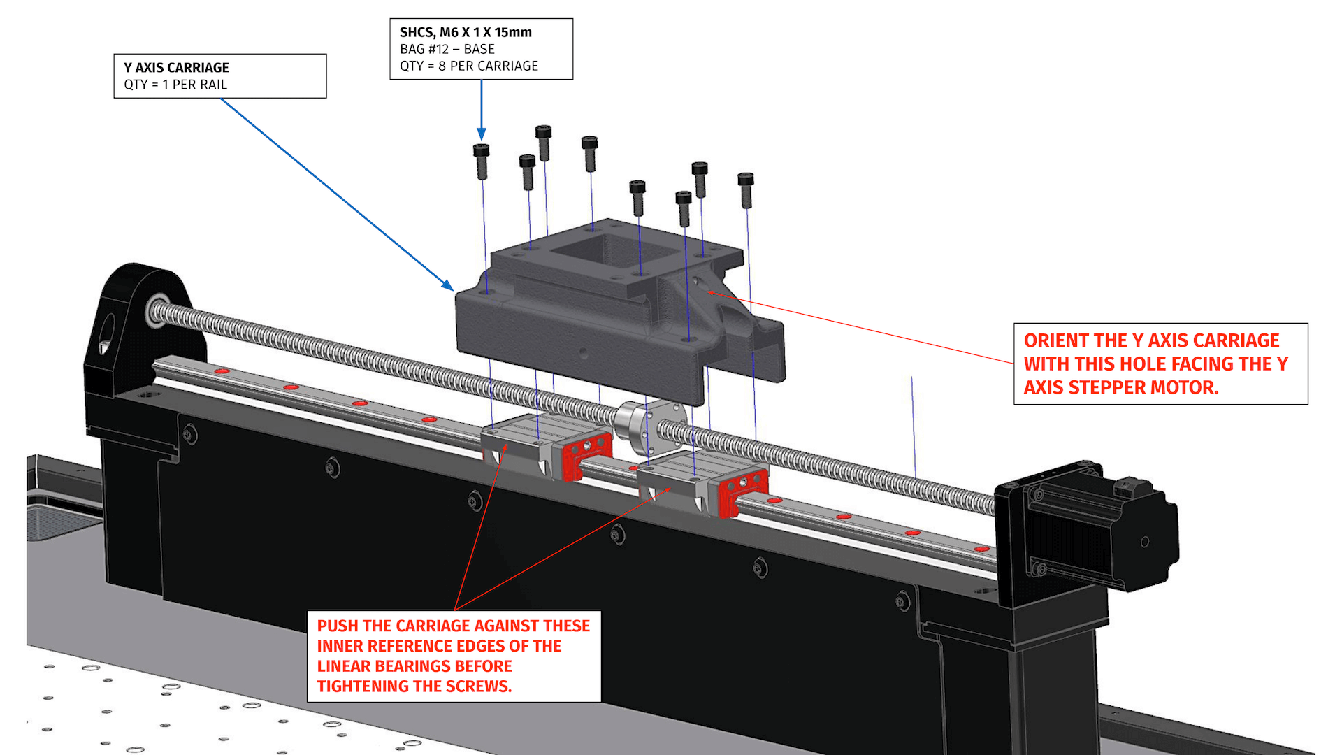
this is the y Rail that will be on both side of the machine, the Top one the ballbearing and ballscrew will be above the linear rail guide, and inside the Y Axis Carriage, so it's below the X Gantry as you can see in this picture how Langmui did it
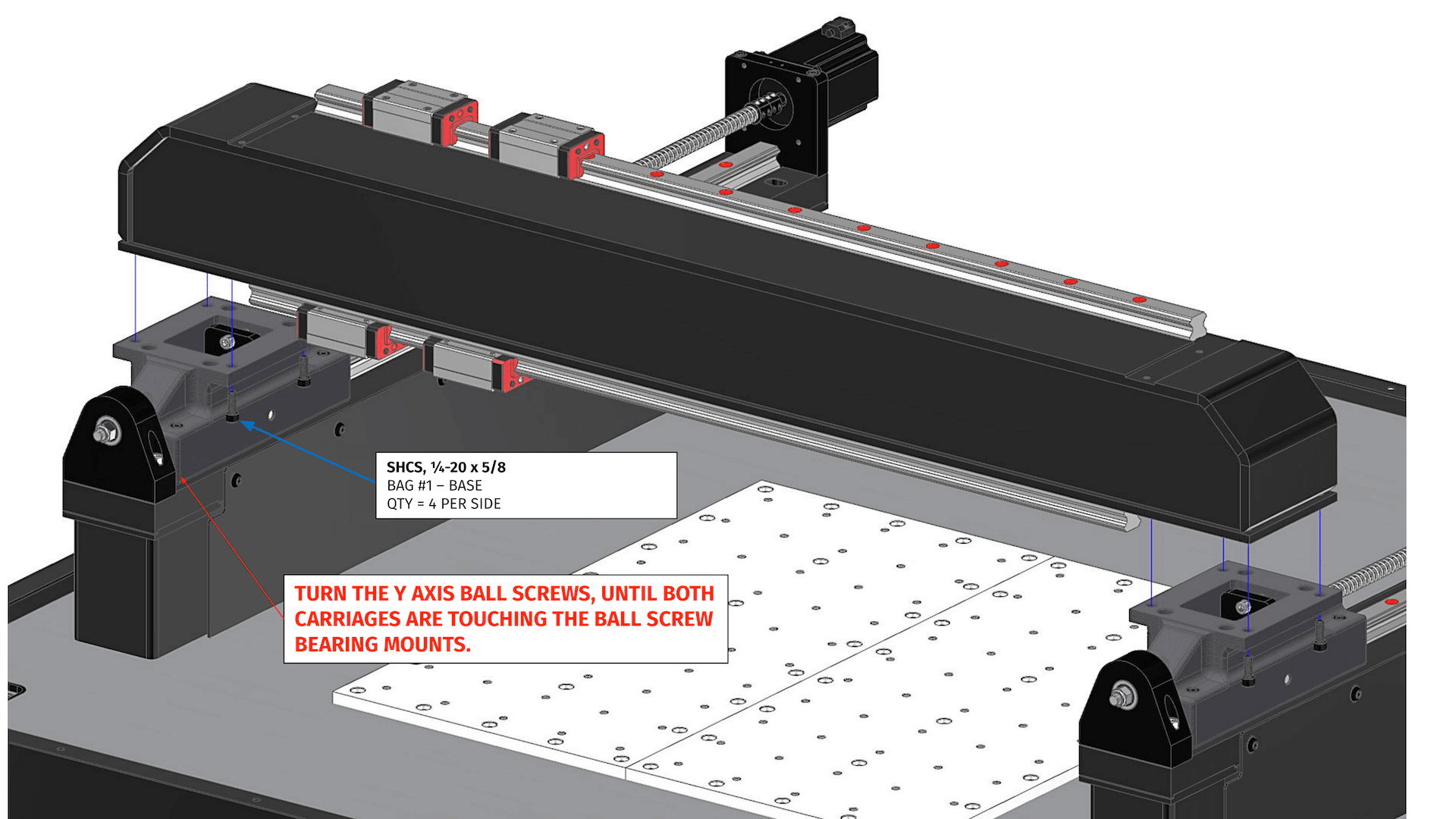
On the other hand, the Bottom one i will move the ballscrew to be away from the linear rail, it will be on the outer side of the machine, so the ballnut will be connected to the Y Axis Carriage by a extended plate as you see in the picture
This design will allow me to have the Y Axis Carriage from almost 70mm to 80mm to be as low as possible almost flush with the Y linear rail about 20mm to 30mm and to have my Y plates width 80mm not 100mm and length 1200mm not 1350mm and that cutting in width and length, it will be replaced by thickness of 40mm not 30mm
So my question is, Dose it matter which way i go with, the force on the ball nut, and the way the Gantry will moved and stability.
-
03-14-2023, 08:14 PM #72
Member
- Join Date
- Jul 2018
- Posts
- 6318
Re: Gantry 3-axis milling machine Design preparation phase
Hi Mogi - Having the ballscrew above the rail is a strategy to minimise the machine footprint. Unfortunately, this also places the ballscrew in a poor position for machine stiffness. It increases the distance from the bearings to the gantry and makes for a complex casting in the MR-1 case. Machine stiffness comes before the drive logic. I would place the screw to the side of the bearings, In fact I would not design the drive system until you sorted the structure then fit the drive to the structure. It does not matter where you push the structure as long as it is reasonable. The structure needs to be stable (bearings as far apart as possible with a square "kern" or footprint. With bushes and bearings with high friction it's important to place drive nuts at the friction centre (otherwise stick slip will occur), but because cars with balls have very little friction the friction centre concept does not exist.
This also allows easier assembly and maintenance. A good machine has major assemblies that stack up like a pyramid. No need to pull things apart to get to bolt heads and nuts and no need to upset drive assemblies to pull top level assemblies apart. Once drives are settled in you don't want to pull them apart to pull the gantry off for instance, sort your structure first... especially your Z assembly it's going to affect your machine footprint. Peter
-
03-14-2023, 08:39 PM #73
Member
- Join Date
- Feb 2023
- Posts
- 66
Re: Gantry 3-axis milling machine Design preparation phase
I'm happy it's like that Originally Posted by peteeng
 I thought I will have to make a complex X carriage, for the footprint it dose not matter that much for me
Yea I can't catch my brain of thinking about this stuff Originally Posted by peteeng
yea I'm preparing the z axis now I should of start from it already, it should be stiff so what come after it don't be effected by it. Originally Posted by peteeng
-
03-14-2023, 10:25 PM #74
Member
- Join Date
- Feb 2023
- Posts
- 66
Re: Gantry 3-axis milling machine Design preparation phase
Hello all, This is my Z axis so far, didn't do any simulation yet, all the plates thickness 20mm, just the bottom bearing support 25mm
Height of saddle 400mm, Width 200mm
Height of Spindle plate 300mm width 200mm
This design is built around 200mm Square Gantry Linear guide rail Top and Bottom so that is another 30mm height
Distance between Gantry bearings 256mm


-
03-14-2023, 10:45 PM #75
Member
- Join Date
- Feb 2023
- Posts
- 66
Re: Gantry 3-axis milling machine Design preparation phase
I feel like i'm doing the simulation wrong here
1000n causing a 4.5micron displacement, i had to remove the linear bearings and no spindle, the force on the z holding plate all of it.

-
03-14-2023, 10:52 PM #76
Member
- Join Date
- Jul 2018
- Posts
- 6318
Re: Gantry 3-axis milling machine Design preparation phase
Hi Mogi - You had better have a meeting with your machinist and figure out how you are going to machine the lands for the gantry rails. As drawn its a two setup job and registering the first land to the second land is going to be tricky especially parallelism. If your going to bolt the cars to the SHS without machining I doubt they will work as the section will be crowned or hollow.
As drawn your saddle will need flanges as when the load pushes fwd or back the middle will bend as the top bearing pushes it in the middle.... Your tool plate (the spindle plate) will need flanges as well
I'd be thinking about part weights and a general philosophy of build. I usually write a small rules list for the build so I don't forget my objectives and limits. Each of my machines has tried to cover various technical and commercial aspects that a one of machine like yours does not need to worry about but its good to have a reference otherwise your thoughts change and then you will always be chasing change.
For instance your gantry is going to be heavy and your unlikely to be able to pick it up and maneuver it unless you use a crane or hoist. One of my rules is no part to be over 50kg prefer 40kg so I can manage it myself. If you have gear then thats OK. The aim at the moment is to get the big picture right and make consistent decisions so your machine is commensurate with your objectives and resources. So you don't paint yourself into a corner....
Although 20mm will do the job I'd look at 25mm bearings they will suit the scale of your machine better and don't cost much more. ... The structure and bearing arrangement is important to get right up front...Peter
-
03-15-2023, 08:50 AM #77
Member
- Join Date
- Feb 2023
- Posts
- 66
Hi Peter, sure I will speak to the person machining the parts for me, the bottom bearing holder it will be a bolted part so it will make it somewhat easier to prepare Originally Posted by peteeng
About flange I will add to saddle and the tool plate based on simulation as much as I can
About parts weight all individual parts will be lower than 40kg just one expection the gantry can be from 35kg to 125kg based on which configuration I go with wall thickness from 10mm to 20mm and square dimensions of 100mm to 200mm
Still researching the benefits of going all the way on the gantry vs the lowest end
I have family to help me carry stuff 2 man with me so it's fine from that part. I can rent hoist to use also if it's required.
-
03-15-2023, 12:18 PM #78
Member
- Join Date
- Jul 2018
- Posts
- 6318
Re: Gantry 3-axis milling machine Design preparation phase
Hi Mogi - This is the arrangement you should be modelling. The force is at the tool, so use a dummy tool with infinite stiffness. Ive attached a guide to machine testing Peter
shooting at 20N/um the spindle plate and the Z plate will need flanges or be very thick. My Z axis is flanged and is equivalent to around 60mm thick steel.
-
03-15-2023, 07:50 PM #79
Member
- Join Date
- Feb 2023
- Posts
- 66
Re: Gantry 3-axis milling machine Design preparation phase
Hi Peter, Dummy tool attacked to the spindle ? also shall I make dummy spindle with infinite stiffness ? since the spindle will be a weak point also ? Originally Posted by peteeng
-
03-15-2023, 08:35 PM #80
Member
- Join Date
- Jul 2018
- Posts
- 6318
Re: Gantry 3-axis milling machine Design preparation phase
Hi Mogi - If you make the spindle infinite stiffness you will make the z axis local stiffness infinite as well. Make the spindle from aluminium and estimate its inside diameter. You can also push on the collet. Once you do this always use the same spindle and stiffness's etc so your apples to apples into the future. I'd moint the spindle to the z axis with some small standoffs so the z axis can move a little. If you "bond" the spindle entirely to the Z plate if will be over stiff. Can you model a friction contact? Peter

 Reply With Quote