


Hi Mogi - I think its overly complex and the actual purpose of the concrete is not apparent. Why don't you model it and find out how much the concrete helps? Plus model a concrete high rail design of same dimensions and compare. They just need to be simple models to give you an idea. This is called a trade study or trade off study. I'm sure if you bond the steel to the concrete it will help, my concern is that it won't be bonded but be mechanically locked in place via the 40 bolts. Then it becomes uncoupled from the structure over time. LMs move to EG is a concern in this respect. There's always some backstory to this sort of change that they will not discuss. Otherwise they would have gone to a high flow concrete which is cheaper then EG. Peter
Mixed media structures are complex and often done for various reasons that don't work out. I'd stay in one environment.
https://en.wikipedia.org/wiki/Trade_study
Results 101 to 120 of 160
-
03-17-2023, 08:36 AM #101
 Member
- Join Date
- Jul 2018
- Posts
- 6322
Re: Gantry 3-axis milling machine Design preparation phase
-
03-17-2023, 09:32 AM #102
 Member
- Join Date
- Feb 2023
- Posts
- 66
Re: Gantry 3-axis milling machine Design preparation phase
Hi peter, You have a point i should check about this, My problem is i'm not trying to build the whole machine based to be 1 part, so i don't have to machine it in 1 time, since i can't do that around me nobody have a huge mill. Originally Posted by peteeng

So i should think of how can i use steel plates for the base that is a parts that can be bolted together and be leveled by simple machining. my head turning now.
I don't wanna use EG because it's more expensive than steel for me.
-
03-17-2023, 09:44 AM #103
Member
- Join Date
- Jul 2018
- Posts
- 6322
Re: Gantry 3-axis milling machine Design preparation phase
Hi Mogi - The usual answer to dancing light machines is to bolt them to the ground. So The machine would be bolted to the stand and the stand to the floor, now it weighs what the earth weighs. This is why industrial robots can move very fast. Some commercial VMC makers recommend floor bolting, some don't.
There are many things to consider in a machine design, you just have to work through all the issues and make the best decision for you. I think your at a spot where you need to rest and settle out a direction then go for it. Peter
addition: I think I have misinterpreted how the concrete base works. The bolts to the bed are preassembled and then pushed into the concrete to the "floor" Now the loadpath is thru the bed to the bolts to the frame. I'm very worried about that because when the concrete uncouples from the frame its nearly free floating. Its only then held on by the embedded walls. Even more evidence why they go to EG.
-
03-17-2023, 09:52 AM #104
Member
- Join Date
- Feb 2023
- Posts
- 66
Re: Gantry 3-axis milling machine Design preparation phase
Yes i will go back to z make sure it's stiff enough, then i move forward from there. Originally Posted by peteeng
-
03-17-2023, 09:54 AM #105
Member
- Join Date
- Jul 2018
- Posts
- 6322
Re: Gantry 3-axis milling machine Design preparation phase
Hi Mogi - Its a valid approach to make the machine in modules that can be transported and machined then assembled and aligned at the point of assembly. That's how machines are designed and made. Its totally possible to make things say in 300mm major dims pieces that exactly align on assembly. Just think about how complex an IC engine is but it all goes together and functions fine. The machine attached is made from 3mm thick steel parts all bolted together and its very stiff. I'm sure upscaling it a bit to a mill would be quite easy. Its assembled using an engineers level, straightedges, stringlines and big squares. It comes out remarkably good if you pay attention to assembly. You can make bigger elements that are bolted together and since they are machined on CNC they can be dowelled. It will be very accurate if you work through the parts sensibly... Plus you will be able to break it down in future and transport it... You need to question every part and every process to realise a great machine. Keep at it.
Your making cost decisions and you have not yet sent a dwg stack to the machinist for a quote, you need to get to that point. Unless the machinist is your brother and will do it for zero or very few $$$ it could be a shock. Peter
The top of the "walls" in this design are the length they are because thats the max length my machinist can fit on his machine. So make the machine in modules that fit the machine it is to be milled on and make them light enough to manage...
-
03-17-2023, 10:15 AM #106
Member
- Join Date
- Jul 2018
- Posts
- 6322
Re: Gantry 3-axis milling machine Design preparation phase
Hi Mogi - You may have noticed you only get flak in this sort of forum. If your not getting flak about something then your probably doing that something right. Forums such as these are poor communication channels but great if you can take the flak, as the flak is what pushes you forward. Peter
-
03-17-2023, 10:37 AM #107
Member
- Join Date
- Feb 2023
- Posts
- 66
Re: Gantry 3-axis milling machine Design preparation phase
Hi peter, i'm here to get educated and get the info from good experienced individuals since i don't have that much experience, so i don't reinvent the wheel from the beginning. Originally Posted by peteeng
-
03-17-2023, 05:32 PM #108
Member
- Join Date
- Jul 2018
- Posts
- 6322
Re: Gantry 3-axis milling machine Design preparation phase
Hi Mogi - I looked at some bonding primers for steel and they are around. If you use concrete/steel I suggest you prime the steel with one, they are generally epoxy based. Here's single component type Peter
https://spf.net.au/products/sika-mon...ete-protection
-
03-17-2023, 08:24 PM #109
Member
- Join Date
- Feb 2023
- Posts
- 66
Re: Gantry 3-axis milling machine Design preparation phase
Thank you peter, i will keep it incase i go with that route, Now i'm playing with the Z design trying to figure out how to do the simulation good on Solidworks, i just started to use it 1 month ago. Originally Posted by peteeng
-
03-17-2023, 09:13 PM #110
Member
- Join Date
- Jul 2018
- Posts
- 6322
Re: Gantry 3-axis milling machine Design preparation phase
Hi Mogi - Your 20N/um is for the whole machine so you need to get a rough machine built and test the whole thing. I usually have a push pull load case in the middle of the gantry with the z down. Then you can establish what each structural "loop" compliance is. This tells you which bits to address. Once this is done you can apportion stiffness to each loop. The loops on a gantry machine are usually the Z axis, the saddle, the gantry, the columns and then the base back to a fixture. With a high rail design its from the wall bearings to the fixture. If your technical this maybe useful. Peter
please note this document states that a low mass machine is desirable and it explains why....
concrete base machine with metal workings - makes good sense to me
https://www.cnczone.com/forums/diy-c...ml#post2546148
-
03-18-2023, 12:21 AM #111
Member
- Join Date
- Jul 2018
- Posts
- 6322
Re: Gantry 3-axis milling machine Design preparation phase
Hi Mogi - I'm interested in your design trajectory because I have been working on a similar sized mill on and off for a few years. I have access to a medium size mill that can machine "our" sized gantry. I have access to heat treat, FEA etc etc. My analyses have taken me on a tortuous journey and your at the start. My first 3 machines were gantry routers with columns to get me going. Then I moved to a high rail design and this is significantly stiffer then priors with no real extra effort. I have played with small castings of concrete grout and like the results. The last 2 machines Scoot-Series 2, then Scoot-Serious 3 machine aluminium quite well. The secret has been in the Z axis and saddle. S3 is considerably stiffer then S2. This is achieved using a I section Z axis and an aluminium billeted saddle vs a steel welded saddle. So the current machine is Frankie and its your size machine but yours will be a bit wider from your rail length spec. So my suggestion is make the base from concrete, if its 1200x1200 and 100mm thick it would weigh 330kg but make its bottom honeycomb so it would weigh 160kg. This can be cast upright then use self levelling to produce the flat top surface. Then it can be drilled and epoxy in thread inserts. The inserts can be cast in if you use a suspended frame that holds the inserts. Probably the way to go....
Then make the rest from steel. Since the walls can be fabricated then TSR then machined they will be accurate. They would be bolted to the base. Need to check that your machinist has the height needed to machine the walls.... The walls could also be cast then topped via levelling or a steel pre-machined top can be epoxied to the top of the wall then levelled via machining... My machines so far have had MDF or Plywood bases but a steel capable mill will need a significant base... I've tried to stay away from steel but its stiffness and low cost keep rising to the top... Keep at it. Peter
-
03-18-2023, 07:45 AM #112
Member
- Join Date
- Jul 2018
- Posts
- 6322
Re: Gantry 3-axis milling machine Design preparation phase
Hi Mogi - I have built a simple block model to demonstrate a trade study model. It does not have bearings or minor features. The intent is to determine the big picture about the concept. Usually there would be another model in the "model" say the walls would be of steel fabrication but rest would be the same. This is then a comparative model not an absolute model.
The aim is to look at the big bits and get a direction of what works and not works. As long as the models are similar its apples to apples. So this model has a Z plate of 50mm thick steel. The gantry is 200x200x9mm 1200mm wide SHS and the rest is concrete with a E=32GPa. I pushed the bottom of the Z plate 0.001mm so the FE figures out how much load it takes to move it 0.001mm. I've attached the step file for your info. Now the take away is that it only took 6N to move it 0.001mm! So the model has no bearings no nuts and bolts etc etc. So we have a long way to get to 20N. The main culprit is the SHS lozenging. And this is the lack of corner stiffness and the poor torsionally shear stiffness of such an SHS.
After I found out the 6N figure I then placed 6N on the edge and checked this was correct which it was... The transverse stiffness is 32N/um so close to target. The vertical stiffness is 54N/um very good...
So build simple comparison models to start with and sort out your main structural philosophy. From prior work a triangular gantry is very good. Since you are going to fabricate the gantry consider a triangle or since you are fabricating it put internal webs if the section is SHS to stabilise the lozenge. The issue with internal webs is that the stiffness varies across the gantry ie if the bearings are at webs its stiff if they are in the interval its softer... maybe a full longitudinal diagonal web is the go. But you can figure that out...
Doing this sort of block study I would aim at +40N/um then move to a more detailed model... Having the bearings on the gantry diagonal it may lozenge less but you can figure that out, update the step file to have the fwd mount and diagonal mount in it and see how it goes. Good Luck Peter
addition - the walls weigh 63kg each and the base weighs 173kg the gantry + z weighs 105kg
-
03-18-2023, 10:45 AM #113
Member
- Join Date
- Feb 2023
- Posts
- 66
Re: Gantry 3-axis milling machine Design preparation phase
Yes i will use your style of designing, build the machine as concept then finalize after i get the result i want. Originally Posted by peteeng
-
03-18-2023, 10:55 AM #114
Member
- Join Date
- Feb 2023
- Posts
- 66
Re: Gantry 3-axis milling machine Design preparation phase
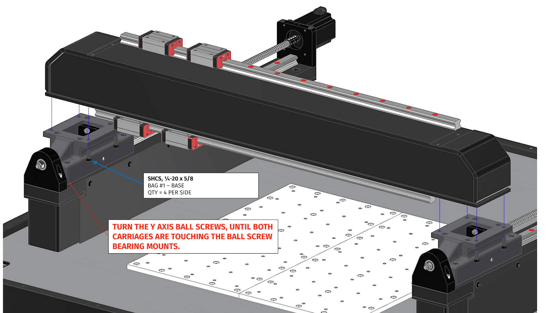
Hi peter, i read your topic from start to finish and i get allot of good information and ideas, for me to machine the walls after fabricate from steel is hard, the way langmuir did it is the best that suit me, like that i can just machine the rails connection to the columns, and the 2 columns on each side, and to make them parallel the bolting will be slotted to allow movement, and i can use shims under 4 corners to fix it. to make sure the rail plate dose not bend because of weight since it's hanging on just 2 points, it's thickness will be about 40mm even can go up to 50mm, more important is a 3mm stiffer plate that will be bolted to the rail when i test it it's showing only 0.6micron deflection when i push with a 1000n in the middle. will keep researching about this concept. Originally Posted by peteeng
-
03-18-2023, 10:59 AM #115
Member
- Join Date
- Feb 2023
- Posts
- 66
Re: Gantry 3-axis milling machine Design preparation phase
Hi peter, I will start to use your simulation program, looking cooler than Solidworks, x Gantry can go up to 20mm thickness with the flange like langumuir and the 45degree bend on the top plate then 90degree Originally Posted by peteeng
Just i'm little busy now on my other job so could't do more research and respond to the fourm.
Thank you for your help.
-
03-18-2023, 11:19 AM #116
Member
- Join Date
- Jul 2018
- Posts
- 6322
Re: Gantry 3-axis milling machine Design preparation phase
Hi Mogi - Since I had a model running I did some variations.
200x200x16mm SHS push stiffness was only a bit better- sorry lost the model
200x200x16mm triangle push 21N/um trans 36N/um vertical 91N/um now the Z plate is bending most
The triangle is the go. Can still have bearings top and bottom... Peter
re 45deg angle is purely aesthetic . It is important to close out the end to improve shear stiffness, But you will need to do some models to get a feel for whats happening...
-
03-18-2023, 11:24 AM #117
Member
- Join Date
- Feb 2023
- Posts
- 66
What is the z travel in this model ? I'm thinking my z travel will be 20cm and bottom of z plate to bed will be max 30cm, also gantry will be 1 meter width supported by 10cm on each side so the linear rail on it will be 80cm width of z will be 20cm so total x travel is 60cm Originally Posted by peteeng
-
03-18-2023, 11:34 AM #118
Member
- Join Date
- Jul 2018
- Posts
- 6322
Re: Gantry 3-axis milling machine Design preparation phase
Its about 300mm but that does not matter in a comparison model. If the geometry is the same in each model that's what's important so the area of interest is clear. In this case we are looking at the gantry and the triangular gantry does best as all other features are identical. Then the z axis needs looking at to get to 40N/um if you want 20N/um in the real machine... Peter
In machine the size you are talking about 200mm Z is too small. By the time you have a wasteboard or a vice and a reasonable tool you will need more than 200mm. Look at commercial mills this size and you will see how big the Z is... What do you want to make? perhaps your machine is too big? Peter
-
03-18-2023, 11:52 AM #119
Member
- Join Date
- Feb 2023
- Posts
- 66
Hi Peter, I'm gonna use the machine for engraving on granit and wood, milling aluminum plates steel plates, but you are right I guess z travel should be more than 200mm Originally Posted by peteeng
But to do that I will have to make the distance between the rail bearing smaller.
-
03-18-2023, 01:19 PM #120
Member
- Join Date
- Jan 2023
- Posts
- 436
Re: Gantry 3-axis milling machine Design preparation phase
Pete I applaud your tenacity, every time someone new comes on, you don't just copy/paste your answers, you literally form them from zero each time and together with simulations at that. If only these guys appreciated what you give them...

 Reply With Quote