


Hi Ard - Probably time to write a book on machine design... Peter
Results 121 to 140 of 160
-
03-18-2023, 02:28 PM #121
 Member
- Join Date
- Jul 2018
- Posts
- 6318
Re: Gantry 3-axis milling machine Design preparation phase
-
03-18-2023, 10:13 PM #122
Member
- Join Date
- Feb 2023
- Posts
- 66
Re: Gantry 3-axis milling machine Design preparation phase
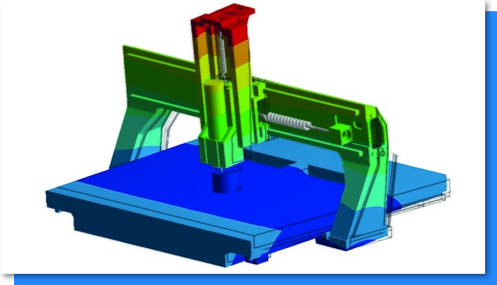
Hello Peter, i made a dummy machine just to do some testing on it, i attracted the step file because when i do simulation on solidworks, it's showing strange result, not effecting the whole frame of the machine. force is 1000n

-
03-19-2023, 02:20 PM #123
Member
- Join Date
- Feb 2023
- Posts
- 66
Re: Gantry 3-axis milling machine Design preparation phase

And here with flagged somewhat similar to Datron M8Cube
It went down to 133/um stiffness
-
03-19-2023, 03:01 PM #124
Member
- Join Date
- Jul 2018
- Posts
- 6318
Re: Gantry 3-axis milling machine Design preparation phase
Hi Ard- thanks, I'm sure everyone who participates is appreciative in some way.
Mogi - The general description then for your machine is a high performance, steel capable hobby machine for mainly flat product. "My" design objective is to make a benchtop 5 axis mill which has taken me to the high wall, high z axis zone. I do moulds and shapely parts like deep bowls. The issue with that is in flat products the Z axis is at its full extension so is at its poorest spot. So we end up designing a machine around its worst operating condition.
So I suggest you seriously consider a rising gantry design. A rising gantry does not have a saddle. Saddles are a big pain to design. They take up space & try to do several things in one spot. If you design one you will find out. So moving the saddle Z axis to the columns is a great idea. The spindle is always at the same height relative to the gantry so its stiff and short. You have a 6 axis controller so 5 axes no problem... They maybe unfamiliar to you but they are out there. Usually in very big machines that would otherwise have very tall wobbly z axes. Here's a small one that punches above its weight. The lowrider. Triangular gantry, lifting gantry.
The other aspect is the spindle and I expect your going to go with a high speed one., Thats Ok as that's the tendency at the moment in high speed machining,. So get a good quality one, water cooled probably ER20 so it can take 12mm tools. or an Er16 which can take a 10mm bit. The Er20 spindle is very big, I find the ER16 to be a good size. Peter
https://docs.v1e.com/lowrider/ Peter
-
03-19-2023, 06:19 PM #125
Member
- Join Date
- Feb 2023
- Posts
- 66
Re: Gantry 3-axis milling machine Design preparation phase
Hi peter, I want to have a z travel similar to langumir one or Datron M8Cube which is about 200mm to 250mm max Originally Posted by peteeng

If i go with 200mm, the spindle + smallest endmill wont reach more than 200mm but the bed 50mm more deep than that, so this extra 50mm is for the vise, maybe i make it little more deep so if i add 4th axis in the future, so i make sure i always have a good usable z depth since almost all the time i will be milling steel or aluminum they will be on vise, the time that i wanna do some wood or granite, i will have spoiled board below them to make up for the missing height on the bed, this board dose not have to be that accurate, it can be mdf and i can surface it with the machine so i have a leveled bed, accuracy with wood and granite is not that critical.
This is Datron z and gantry design that is looking good, will try to implement it and see what i get in my height rail design
even i thought about having a poket in my bed like 100m deep or more to allow of adding 4th and 5th axis similar to this
I'm thinking as first it will be 2.2kw ER20 80mm Spindle, later it will be a ATC 3.2KW 110mm like this one Originally Posted by peteeng
https://www.aliexpress.com/item/32978751204.html
-
03-19-2023, 09:07 PM #126
Member
- Join Date
- Jul 2018
- Posts
- 6318
Re: Gantry 3-axis milling machine Design preparation phase
Morning - seems my last entry didn't make it?
Ard - I'm sure people are appreciative of all the input everyone gives here
Mogi - from your information lets describe your machine as - a high performance hobby level Mill, steel capable, for mainly flat product.
"My" mill trajectory has taken me to the high rail, high Z axis config because I do moulds and large deep contoured parts like bowls and I'm working towards a 5 axis machine which needs a high Z axis. Where your heading I recommend you build a rising gantry machine. These have no saddle which means the Z axis is very stiff no matter its height as the z axis is moved to the columns. So a small wall then moving columns with a rising gantry.
A conventional gantry machine is at its poorest condition cutting flat objects as the Z is mainly down and at its longest. So the design is optimised on its worst condition which is poor. The machine should be designed for what it has to do. Here is a small lifting gantry design that punches above its weight. https://docs.v1e.com/lowrider/ triangular gantry, lifting gantry
Most lifting gantry machines are on very very big machines to stop have a huge z axis, but there are small ones in the forum. Also your spindle. I expect you'll go for a high speed spindle. If its a good quality one it will cope with steel. You will have to run it slow so a water cooled one is good. You will need to feed fast using high speed machining techniques so high pitch ball screws are needed. ER20 (12mm max) or ER16 (10mm max) are the picks. Keep at it. Peter
-
03-19-2023, 09:12 PM #127
Member
- Join Date
- Feb 2023
- Posts
- 66
Re: Gantry 3-axis milling machine Design preparation phase
It arrived, and i responded do it, not sure what is wrong with the forum, on my mac device i can't see past the 6th page, on my mobile device same, only on my windows laptop i can see them
-
03-19-2023, 10:26 PM #128
Member
- Join Date
- Nov 2013
- Posts
- 4358
Re: Gantry 3-axis milling machine Design preparation phase
Hi,
what about using a granite surface plate or a cast iron surface plate as the base?
Craig
-
03-19-2023, 10:53 PM #129
Member
- Join Date
- Jul 2018
- Posts
- 6318
Re: Gantry 3-axis milling machine Design preparation phase
for some ideas
https://youtu.be/qlj41jGXuHk
-
03-19-2023, 11:21 PM #130
Member
- Join Date
- Jul 2018
- Posts
- 6318
Re: Gantry 3-axis milling machine Design preparation phase
Hi Mogi - with a gantry machine you will find its spindle will come fwd of the bed and have dead space at the rear. The fwd bit can become a "pit" if you want (rotaries, trunnions etc can live there). I use the fwd bit as an apron. ie a vertical bed on the front of the machine so you can do edge work. You can use a combination of pits and bolsters. (bolsters are blocks you place on the bed to raise the job) to use the machine in a stiffer position. Consider the raising gantry solves many problems. Peter
-
03-20-2023, 04:41 AM #131
Member
- Join Date
- Jul 2018
- Posts
- 6318
Re: Gantry 3-axis milling machine Design preparation phase
Hi Mogi - Just been sent this by a local person. Its going to be a 5 axis machine. He cut the back off (the dead space) and added it to the front. Its also a concrete casting quite nice. Peter
-
03-20-2023, 09:25 AM #132
Member
- Join Date
- Feb 2023
- Posts
- 66
Re: Gantry 3-axis milling machine Design preparation phase
The main structure of the machine that is touching the ground will be steel tube table above it steel sheet that is like a box inside it the y rail supports will sit on 3 point of contact then I will pour concrete around it with height of about 10cm then impede 15mm steel plate in the concrete using many long screws to bond to concrete Originally Posted by joeavaerage
If I go with granit i will require too big size granit same for cast iron
But the steel plate it will be only where is my machine can cut not the whole surface
Concrete will be covered with epoxy as finish.
-
03-20-2023, 09:26 AM #133
Member
- Join Date
- Feb 2023
- Posts
- 66
Re: Gantry 3-axis milling machine Design preparation phase
Good design I will start to investigate the triangle gantry with linear rails and ballscrew facing front, having slots in the plate that make up the gantry improve bending as I know so it's better than flat plate. Originally Posted by peteeng
-
03-20-2023, 09:30 AM #134
Member
- Join Date
- Feb 2023
- Posts
- 66
Re: Gantry 3-axis milling machine Design preparation phase
Hi Peter, how they making the surface below linear rails flat ? Machining it after casting, I couldn't get this yet. Originally Posted by peteeng
-
03-20-2023, 10:53 AM #135
Member
- Join Date
- Jul 2018
- Posts
- 6318
Re: Gantry 3-axis milling machine Design preparation phase
Hi Mogi - The ideal way is to bond the metal to the concrete then take it to a machinist for levelling, The other way is to have the steel or aluminium bits machined then bond them to the concrete paying attention and leveling as you go. You can use jacking screws on the parts or spacers/shims. Then dam the edges and pour epoxy into the gap. Similiar to how I do mine, I get the metal bits machined then I use straight edges and levels to set the parts up as best is possible. Peter
also with concrete you can set up the parts and use a self levelling grout to level the top. If you place the two walls together and bridge them you can self level the tops and get them to be identical heights. Similar to how many people do epoxy levelling. But SL concrete can be used much thinner then epoxy down to 1-2mm. Peter
-
03-20-2023, 12:55 PM #136
Member
- Join Date
- Jan 2023
- Posts
- 436
Re: Gantry 3-axis milling machine Design preparation phase
the bed looks solid, but that gantry to support a 2 axis spindle assembly? he could have doubled the height of it and cast it just like the bed. I have a feeling it's going to be one of those feeble belt driven 2 axis setups. Well time will tell. Encourage him to make a build thread... Originally Posted by peteeng
-
03-20-2023, 07:06 PM #137
Member
- Join Date
- Feb 2023
- Posts
- 66
Re: Gantry 3-axis milling machine Design preparation phase
Hi Peter, yes this is the best way but I can't do it Originally Posted by peteeng
Using spacers or shims can cause a problem, I will have to add shims on the whole length, if I only add at the begin and end, the middle will be unsupported Originally Posted by peteeng
I thought about using Jacking screws, similar to how the Big Gantry mills using as you see in this video 1:45 time
https://youtu.be/ADMbLSykYjE?t=106
This is a good idea also to think about, to pour epoxy after finishing with the alignment is a good idea to fill all the gaps so the whole rail be supported. Originally Posted by peteeng
-
03-20-2023, 08:31 PM #138
Member
- Join Date
- Jul 2018
- Posts
- 6318
Re: Gantry 3-axis milling machine Design preparation phase
Hi Mogi - For epoxy to self level it needs to be around 6mm thick. Due to its exotherm expansion and its curing process in "cells" it crawls if done thinner and will not be flat. 6mm of epoxy is very rubbery (E=3GPa) to mount mechanical parts on that require stiffness. I do not recommend you use epoxy for levelling. Self leveling concrete grout however is stiffer E=30GPa and it can be cast thinner. 2-3mm so is the better material for the intent. Using liquid epoxy or epoxy putty as a small gap filler or shim or part setter is fine. Peter
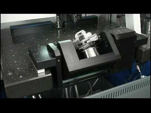
In the Mori video you can see they use water levelling for the bed set up. Interesting in this day of lasers they still use water. I suppose water allows them to go around corners vs laser has to be line of sight. So build a water level... there are commercial water levels that are very very accurate...
-
03-20-2023, 11:08 PM #139
Member
- Join Date
- Jan 2023
- Posts
- 436
Re: Gantry 3-axis milling machine Design preparation phase
Those aren't your simple jacking screws, those are unisorb fixators, regular jacking screws wont work because you won't be able to align the rails parallel to each other. You can use segmented steel pieces (with an anchor each) under each rail bolt hole instead of a long steel piece. Similar to DMG's µPrecision, of course you'd still have to have them ground or do it slowly by hand, sanding each of them to required spec. Originally Posted by Mogilogi
https://www.youtube.com/watch?v=nJ5KmGPD5Iw
-
03-20-2023, 11:39 PM #140
Member
- Join Date
- Jul 2018
- Posts
- 6318
Re: Gantry 3-axis milling machine Design preparation phase
Where do I get the u bubbles?
 Peter
Peter

 Reply With Quote