


Originally Posted by lucas

Thanks Lucas,
I will contact the seller,
Best regards
Terry
Thread: Rotary table indexer
Results 601 to 620 of 815
-
01-07-2013, 07:48 AM #601
 Registered
- Join Date
- Feb 2007
- Posts
- 33
-
01-07-2013, 03:36 PM #602
Gold Member
- Join Date
- Jan 2010
- Posts
- 2141
Unfortunately, no. All stepper motor drivers are not created equally, so to speak. It's necessary to examine the details to understand what functionality is provided by a particular "driver" and what is not. Originally Posted by terryd15
The rotary table indexer circuit outputs step and direction signals which in turn are used to control a driver that is designed to accept step and direction signals as its input.
The aforementioned L298 driver board is not capable of accepting step and direction inputs by itself. Rather, it only comprises the electronics that can energize two coils in one polarity or the other. Additional circuitry would be required to provide the logic that translates the step and direction signals into the proper sequence of coil energization and de-energization that will result in the desired movement of the motor. Other circuitry could also be added for the purpose of limiting the current drawn by the motor, or for microstepping, or other desired features.
There is an IC called the L297 (that is designed to handle some of that functionality) which is often paired with the L298, however the board to which you linked does not have the L297 circuitry built in.
As an alternative, theoretically you could modify the firmware of the indexer board to handle the required logic, however my understanding is that the source code for the indexer has not been made available, and so that task would entail designing and coding all of the logic from the ground up, which would be a major undertaking.
-
01-07-2013, 04:20 PM #603
Registered
- Join Date
- Jan 2005
- Posts
- 364
The silk for the transistor is correct. Originally Posted by homerandmarg
All 3 are BC337, for Q3: pins from top to bottom C B E (viewed from component side). Emitter is connected to ground.
-
01-07-2013, 04:31 PM #604
Registered
- Join Date
- May 2006
- Posts
- 184
Hi Simon, I'd go with post #33 (I'd probably actually tried those to make sure they work). I haven't checked the circuit diagram so can't comment - but that was drawn from the finished circuit. (I built it on a breadboard then drew the circuit once it worked...)
My pcb layout was checked with the Farnell keypad, beyond that...
Most keypad problems can be resolved by considering the keypad to be two sets of 4 wires.
If the keypad is rotated 90 degrees (i.e. the rows and columns are swapped) then swap the two sets wires over.
Then if the keypad is flipped top to bottom flip over the 4 row wires.
Finally if the keypad is flipped left to right flip the 4 column wires.
(It helps here if the keypad cables are two reversible 4 pin plugs...)
If I knew then what I know now I'd have added the ability to reprogram the keypad from the software! (Perhaps if I get some spare time)
Cheers,
Steve.
Originally Posted by homerandmarg
-
01-07-2013, 08:33 PM #605
Registered
- Join Date
- Apr 2007
- Posts
- 10
 winning
Hi guys
My indexer is up and running and just needs boxing up.
I must thank all of you who took the time to help me get to this stage it is most appreciated.:cheers:
Thanks especially to Steve Ward for software and support and to Lucas for the board design.:cheers:
I will try and add photos when its complete. :wave:
-
01-07-2013, 10:30 PM #606
Registered
- Join Date
- Feb 2011
- Posts
- 0
Thanks Steve & Lucas,
It pays not to do stuff late at night when I should really be getting some zzzzzzzz!
I have a cheapie keypad (Same as Jhovel) and the pin placement seems to follow no known standard! With the keypad you used, the keys can be labelled at will and so it opens up many combinations. Should have gone with that!
Lucas, I never doubted you! Like I said, late at night things seem a little fuzzy...
On another note, I'm planning on using this stepper driver with a nema 23 stepper motor for my 8 inch RT.
Single Axis TB6560 3.5A 2 Phase CNC Stepper Motor Driver Board Controller | eBay
It says the inputs are optically isolated and so needs input resistors. It states a 1K resistor for 12V controller signals, so could I get away with a 500 ohm from the controller given the approx 5V outputs? That's about 10mA output, would the chip do this or should I add a couple of output transistors to drive the output and keep the current low
Thanks,
Simon
-
01-08-2013, 09:59 AM #607
Registered
- Join Date
- May 2006
- Posts
- 184
Roughly speaking 12v and 1k is around 10mA.
(12v minus 2v for the led forward voltage drop divided by 1k).
So for 5v you need 3/0.01 = 300, so call it 270 ohms.
10mA is well within the current source/sink capabilities of the chip so I wouldn't worry.
-
01-08-2013, 10:05 AM #608
Registered
- Join Date
- Feb 2011
- Posts
- 0
Once again, thanks Steve! Originally Posted by kwackers
Simon
-
01-09-2013, 03:10 PM #609
Registered
- Join Date
- Feb 2007
- Posts
- 33
Hi,
I have a 4" rotary table similar to this one. What size motor can I get away with, does anyone have any suggestions. ARC Eurotrade suggest a 180 Ncm stepper, That seems a bit overkill to me, what have others used on this size table (1:72 worm ration).
Besrt regards
Terry
-
01-09-2013, 05:33 PM #610
Registered
- Join Date
- May 2006
- Posts
- 184
You could certainly use a smaller motor, probably I'd go for the same 'footprint' but half length. Originally Posted by terryd15
(Although unless you need a smaller one I'd be inclined to go with the 180).
I use a 180Ncm one on my 4 & 6 inch tables (1:90) and I often bolt the 4 inch version to the rear of my lathe to directly drive the lathe head for indexing which it does with ease.
-
01-09-2013, 06:41 PM #611
Registered
- Join Date
- Feb 2007
- Posts
- 33
Hi,
Sorry about this, it appears to have posted twice, Thanks Steve for your comment, much appreciated,
Besrt regards
Terry
-
01-10-2013, 07:03 PM #612
Registered
- Join Date
- May 2006
- Posts
- 25
Thanks Steve
Got mine working.
Redrew the schematic and board in eagle if anyone wants to use it.
cad files.zip
-
01-10-2013, 09:16 PM #613
Registered
- Join Date
- Nov 2007
- Posts
- 14
Hi Sam,
Nice job. I especially like your keypad. How did you go about making that up?
Joe
-
01-10-2013, 11:07 PM #614
Member
- Join Date
- Jan 2006
- Posts
- 204
how much to cut me one of those boards and point me to the correct parts list. including display
Thank You
archie =) =) =)
P.S. I have an older circuit card that I cannot see well enough to drill and other issues lol
-
01-10-2013, 11:51 PM #615
Registered
- Join Date
- May 2006
- Posts
- 25
keyboard
keyboard is from ebay, just put labels under caps. Originally Posted by joegib
1x White Keyboard 4x4 keys 16 keys Metal Panel, combined type keyboard | eBay
-
01-11-2013, 12:16 AM #616
Registered
- Join Date
- May 2006
- Posts
- 25
Display
Display is also from ebay. Originally Posted by jeep534
HD44780 2004 20x4 White Characters LCD Display Module | eBay
I just made the board on my cnc mill, I just do it as a hobby sorry. You can see if someone else can make the board for you.
Sam
-
01-14-2013, 10:54 AM #617
Registered
- Join Date
- Feb 2007
- Posts
- 33
Hi Archie, Originally Posted by jeep534
I can't cut a board for you (I do have a spare but am in the UK) but the correct parts list with display details are in the file attached to the first post on this thread (by Kwackers - aka Steve) I found that Lucas' design (page 29 post No 346) is easy to produce using the toner transfer method for pcb'
Best regards,
Terry
-
01-19-2013, 04:34 PM #618
Registered
- Join Date
- Nov 2007
- Posts
- 14
Calling Sam Waters
Hi Sam,
I've now obtained the keypad type you used and I certainly like the tactile feel and the ease with which I'll be able to apply lettering — see pics below:
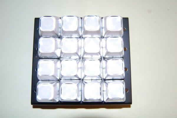
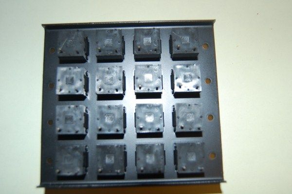
One thing surprised me though — the keypad is simply a 4 x 4 array of switches with no circuitry or wiring between the contacts. Can you explain how you handled this please — did you make a PCB or a matrix of wiring?
Joe
-
01-24-2013, 08:18 PM #619
Registered
- Join Date
- May 2006
- Posts
- 184
Hi Joe, did you figure out how to wire your keypad?
-
01-25-2013, 11:32 AM #620
Registered
- Join Date
- Nov 2007
- Posts
- 14
Hi Steve,
Only up to a point. In terms of literal hardwiring it's easy enough — two sets of 4 wires arranged at right angles, one set being being soldered to the 'row' pins, the other set to the 'column' pins, ensuring that the physical crossover points of the two sets of wires are insulated from one another. Then connect the tails from each set of wires to the control PCB as per the circuit diagram.
Ideally, though, I'd like to do this using a PCB. I've looked at some of the PCB layouts posted by other members who've made up keyboards based on loose key switches. Trouble is, the loose switches commonly incorporate active pins plus 'structural' pins, the latter not doing anything electrical but only providing additional support on the PCB. So, in looking at other peoples' PCBs I'm having trouble sorting out which solder pads are doing the active work and which are only along for the ride. In the case of my unit, of course, I only need 2 pads per key switch. Anyway, I'll soldier on or call out for help. If I work it out I'll post the solution.
Thanks
Joe

 Reply With Quote
Similar Threads
-
Stand alone rotary table indexer.
By kwackers in forum PIC Programing / DesignReplies: 13Last Post: 01-29-2023, 03:01 PM -
CNC Rotary Indexer/Table
By desman in forum Commercial CNC Wood RoutersReplies: 2Last Post: 08-11-2015, 03:32 PM -
4th Axis CNC Rotary Indexer Table Plans
By Modular CNC in forum News AnnouncementsReplies: 4Last Post: 05-11-2011, 07:55 PM -
Manual indexer-rotary table vertical
By silverfoxx03 in forum Want To Buy...Need help!Replies: 0Last Post: 02-18-2011, 09:04 PM
