


Waiting is over: parts arrived today.
Pic programming went fine.
But after assembly: nothing on the LCD: no blocks, backlight OK but no text, good thing: buzzer beeps on keyboard press.
Looks like the Pic is OK but something wrong with the LCD.
After a long search (didn't want to experiment and fry the LCD) it seems that the contrast input needs a negative voltage.
I used a 9V battery and some wiring changes to create a negative voltage.
And yes it works, contrast input needs to be approx. -2.9V.
Now I know why this LCD was the less expensive one.... bummer.
But this confirms that the latest PCB layout is OK IF you have a "normal" LCD.
Too late for pictures now, need my bed.
Maybe more tomorrow.
Thread: Rotary table indexer
Results 361 to 380 of 815
-
02-14-2011, 11:00 PM #361
 Registered
- Join Date
- Jan 2005
- Posts
- 364
New PCB saga continues
-
02-14-2011, 11:36 PM #362
Registered
- Join Date
- Oct 2005
- Posts
- 2392
Wow! Where on earth did you find an LCD that needs a negative contrast voltage in this day and age?
 I thought they stopped making those in the '80s.
Khalid- Nice machine shop and nice controller you made too!
-
02-15-2011, 07:42 AM #363
Registered
- Join Date
- Sep 2006
- Posts
- 37
Hi Steve Can you help please the stepper board I have has the connections
+5V
GND
CP
DIR
INC
DEC
can you tell me which conection on my stepper driver board goes to which pin on your indexer board.
Thanks Bob
-
02-15-2011, 05:58 PM #364
Registered
- Join Date
- Jan 2005
- Posts
- 364
That's what I thought as well, it didn't come from "Ebay: old inventory" but from Farnell ordercode: 1671508. Originally Posted by RomanLini

To everybody: PLEASE don't order this one.
Below are a few pics of the assembled unit.
The white and red wires are the changes needed to inject the negative voltage for the contrast, this is temporary: I will either use a DC-DC convertor to create the negative voltage or use a normal display.
I soldered a female header on the LCD and long header pins on the PCB so that they can easily be seperated for updates.
The black wires are the power supply, I used a scope to measure the step/dir output and they are there.
For me this is the definitive version unless some of you would like other hardware features.
-
02-17-2011, 01:59 PM #365
Registered
- Join Date
- May 2006
- Posts
- 184
Hi, sorry if anyone has asked me questions and I've not replied. I've stopped getting notifications from this thread (again).
Usually it's pretty quiet but it seems to have been pretty busy lately!
@Khalid. Excellent videos! I feel quite humbled seeing my little controller on such huge machines! If it's ok I'd like to use those videos on my website (when I finally get around to making one...)
If anyone has asked a question of me to which I haven't replied please do so again, probably better either via PM on this site or via the email address in the instructions (or in the setup - if you've got it working).
I can only have a stab, but I'd guess CP is clock pulse, so connect that to 'step' and DIR to 'dir' (and obviously GND to ground). Originally Posted by redpiperbob
If as I'd assume you also need to provide a 5v supply this can be taken from the line marked 5v on the power socket.
Steve.
-
02-17-2011, 02:17 PM #366
Gold Member
- Join Date
- Apr 2006
- Posts
- 3498
Hi Steve, I will be humbled if you use the videos at your website.... I am thinking of addition of your controller to Boring machine rotary table.
I would be grateful if you can give us a solution to our Lathe Machine. I have seen an open source "Electronic Lead Screw" for lathe. But that is very complex. Can you start a new thread on programming of similar system?
Electronic Lead Screw Main Page
My Regards to you
http://free3dscans.blogspot.com/ http://my-woodcarving.blogspot.com/
http://my-diysolarwind.blogspot.com/
-
02-19-2011, 04:13 PM #367
Registered
- Join Date
- Jan 2005
- Posts
- 1050
apologize for being Off topic - Khalid did they name the block after you - khatti Block
-
02-19-2011, 04:21 PM #368
Gold Member
- Join Date
- Apr 2006
- Posts
- 3498
I wish when i retire from service i have a name like that Originally Posted by contactirfu
.. One of our Unit Manager (you can see standing 2nd from right to left in the above picture) retired from service and acknowledging his contributions we named one of the building..
http://free3dscans.blogspot.com/ http://my-woodcarving.blogspot.com/
http://my-diysolarwind.blogspot.com/
-
02-20-2011, 10:59 AM #369
Registered
- Join Date
- Sep 2006
- Posts
- 37
Hi All I sent this email to Steve(qwackers) But I would apreiciate anyone who has an idea of what I have done wrong.
"Hi Steve
I hope you dont mind me emailing you direct . But you said you were not getting notifications of the rotary table forum posts.
I have a problem with the build I get a blank row 1 all the pixels lit in row 2 a blank row 3 and all the pixels light in row 4.
specs are 12vdcVin
5 Vdc on pin 1.7.8.9,11,18,30,32,38,39,40
0.12 on pin 2
I have a USB scope on my laptop that I put on the Xtal and it is giving me 10mhz
I used winpic800 to programme and verify the 18f452 all seemed ok.
I have attatched a screen dump of the config page."
Can you suggest something please
Bob
[IMG]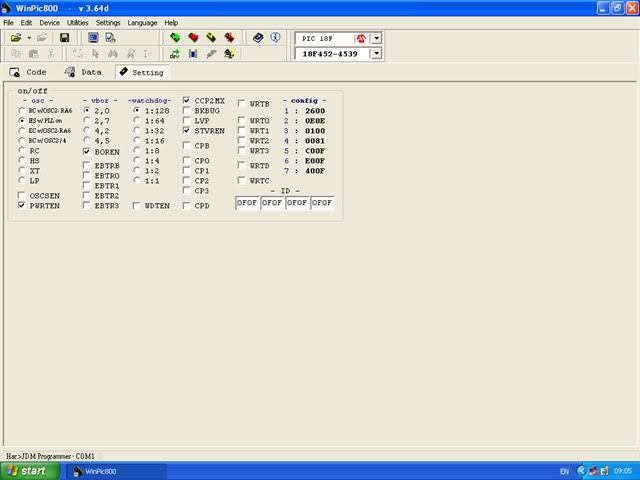 [/IMG]
-
02-20-2011, 12:07 PM #370
Registered
- Join Date
- May 2006
- Posts
- 184
Hi Bob,
Nothing jumps out from that...
The display you describe is a classic uninitialised LCD. It's by far the most common fault and basically means either the processor isn't running or there's a fault between it and the display.
First thing is to see if there are any signs of life, do you have the beeper connected? If so does it beep if you press a key?
(If you've a scope you can check the beeper output pin on the pic directly, every time a key is pressed you should see a burst of pulses.)
If you don't have a keypad yet - you can simulate one simply by shorting two of the pins on the keyboard connector - between any in the first group of 4 with the second.
If the processor isn't running, check power to the processor (and pin 1/mclr) and the circuit around the xtal. That's pretty much all that's required to make the processor run.
If the processor is running the problem is almost certainly the connections to the LCD. Remove the processor and referring to the circuit diagram check for continuity between each of the processor pins and the relevant LCD pin.
Then check for short circuits between adjacent processor pins that drive the LCD.
Hope this helps
Steve.
-
02-20-2011, 12:19 PM #371
Registered
- Join Date
- Sep 2006
- Posts
- 37
Hi Steve thanks for that.
Yes I do have a beeper attacthed and it is working when I press a button.
I will look at the lcd connections.
Thanks once again
Bob
-
02-20-2011, 03:17 PM #372
Registered
- Join Date
- Sep 2006
- Posts
- 37
Hi Steve its gone from bad to worse no beep now and no freq from Xtal.
I think I have blown the pic. although it still verifys But that only uses the prog pins.
if i press a button I some times get a beep but mostly several weaker sounds and now and again I loose the blocks of the lcd or I get an arrow on the display .
thanks anyway
Bob
-
02-21-2011, 12:38 PM #373
Registered
- Join Date
- Oct 2010
- Posts
- 93
@ Luc: I'm just finishing my rotary table controller on your excellent PCB layout, which came out beautifully using print-peel-etch .
I seem to have overlooked your addition of C8 to the circuit (next to the display trimpot. What is its value, please and what does it do?
Cheers,
Joe
PS: will post pictures when I get a little further advanced.Joe in Aus
-
02-21-2011, 12:44 PM #374
Registered
- Join Date
- May 2006
- Posts
- 184
@bob
If you get a beep the PIC should be running (i.e. the 10mhz must be present). It's notoriously difficult to look at signals around the OSC pins due to the impedance, often you stop the clock simply putting a probe on the pins.
Did you find any issues with the connections to the LCD? Sometimes if it's not initialising properly you will get random characters displayed.
It's not unknown for PIC's to be dead and still verify. I've had a couple do that to me over the years. I've also had some that are not driving pins properly - although that's rarer.
-
02-21-2011, 02:59 PM #375
Registered
- Join Date
- Oct 2010
- Posts
- 93
Steve, would you mind very much posting an updated circuit, please?
The only one I can find (ver 2.0) does not show the backlight resistor, and shows 2 x 100nF capacitors - your build PowerPoint shows 4 of them (the silk screen only shows 2 as well, BTW).
I ended up giving up on the layout you published, because once I had etched, it, there were several poorly separated tracks that I spent a couple of hours cleaning up with a scalpel under a big magnifying glass - but could not get right. The tracks and gaps were both far too narrow for my eyes and etching skills.
I ended up etching Lucas'layout and that came out nice.
I've finished assembling it tonight, but must have made a mistake somewhere, because I can't get it to even give me 5V at the powersupply.... back to the drawing board....
Too tired now to do any fault tracking.....:devious:
Cheers,
JoeJoe in Aus
-
02-21-2011, 03:11 PM #376
Registered
- Join Date
- Apr 2008
- Posts
- 57
Does anyone have something to linear motion?
-
02-21-2011, 05:57 PM #377
Registered
- Join Date
- Sep 2006
- Posts
- 37
Hi Steve no i did not find anything with the display joints although I did go over them again I could not find any shorts or dry joints on the strip board. so I dont know where to go from here.
Bob
-
02-21-2011, 11:46 PM #378
Neuer Benutzer
- Join Date
- Mar 2007
- Posts
- 7
if anyone has converted asm on Rotary table indexer of atmel microcontroller
-
02-22-2011, 04:13 PM #379
Registered
- Join Date
- Oct 2010
- Posts
- 93
Well, my rotary controller now works!
I took an uneducated guess at the capacitor values. Turns out I also had a "weird" switch pad: I had to split the connector and slice the "robbon" cable (8 printed conductors on spme sort of clear film) and turn over one half of these. Very odd... never mind, it took a fair bit of messing around with 8 bits of wire to figure that out.....
Now I can assemble the unit. Have to find a nice small 24V DC power supply to fit inside the smallish aluminium enclosure. I want to make it completely self contained with just a powere cable going in and a 4-pole cable going to the stepper motor. Will look nice.
Thanks kwackers and lucas for all your nice design work - and all participants in the development!
Rotary table getting closer to completion too.
I look forward to making chips on it!Joe in Aus
-
02-22-2011, 11:18 PM #380
Registered
- Join Date
- May 2006
- Posts
- 184
@jhovel
Glad it's working.
With regards your earlier questions. The powerpoint is for an earlier version, the correct circuit should only have two 100nF caps. However the powerpoint does show roughly how to build it.
The backlight circuitry isn't shown because to some extent it may depend on your LCD. (Or your LCD may not have any).
Since most LCD's now conform to the standard of using a series resistor then I could probably add it, but tbh it's not really worth the hassle since it's only a single resistor.
Other than that the last circuit diagram published is correct.

 Reply With Quote
Similar Threads
-
Stand alone rotary table indexer.
By kwackers in forum PIC Programing / DesignReplies: 13Last Post: 01-29-2023, 03:01 PM -
CNC Rotary Indexer/Table
By desman in forum Commercial CNC Wood RoutersReplies: 2Last Post: 08-11-2015, 03:32 PM -
4th Axis CNC Rotary Indexer Table Plans
By Modular CNC in forum News AnnouncementsReplies: 4Last Post: 05-11-2011, 07:55 PM -
Manual indexer-rotary table vertical
By silverfoxx03 in forum Want To Buy...Need help!Replies: 0Last Post: 02-18-2011, 09:04 PM
