


Excellant show of Workmanship with good & simple design. Your machine build has inspired me to make one. Can you just breif me the exact specs of the machine and the constant possibility of machining Steel on long run. As i am a novice in building machines please share your ideas which would be really helpful in building one.
Thread: Slant bed CNC lathe from scratch
Results 241 to 260 of 405
-
03-29-2009, 06:47 PM #241
 Registered
- Join Date
- Apr 2007
- Posts
- 90
-
05-29-2009, 08:45 PM #242
Registered
- Join Date
- May 2006
- Posts
- 573
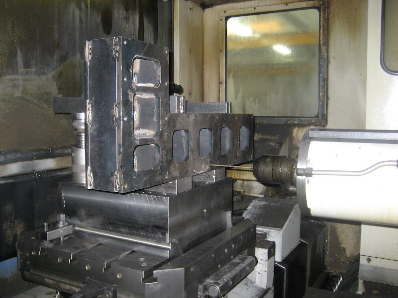
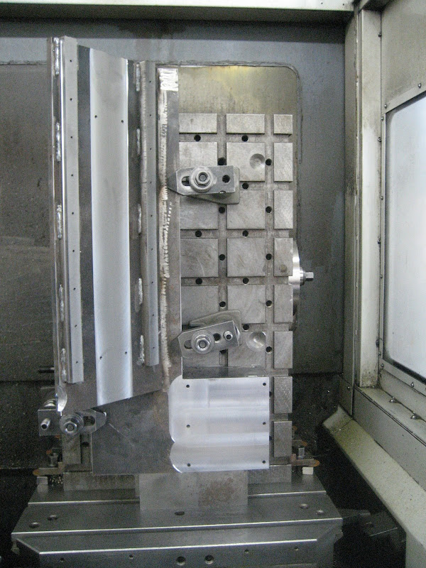
Finally some update. I droped off the base at my uncles mid december, but nothing has happend until today, so lets just say that it has now "aged". Anyway, they have a nice big 4 axis machine, capable of machining workpieces up to Ø900x900 and 1200kg.
Here is a picture of the first setup, machining the bottom and ends
From KX3

From KX3
Envy...
From KX3
From KX3
Second setup
From KX3
Machining finished
From KX3
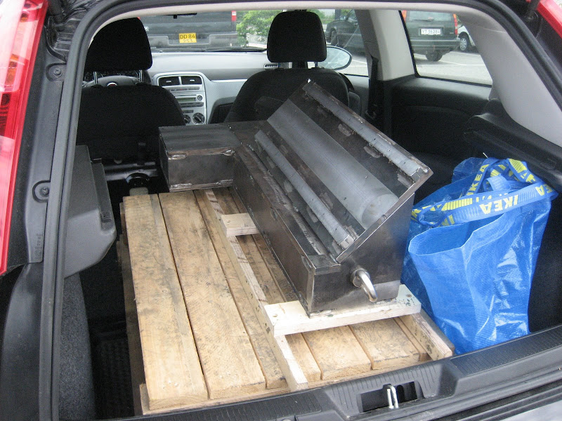
Fits right in a punto
From KX3
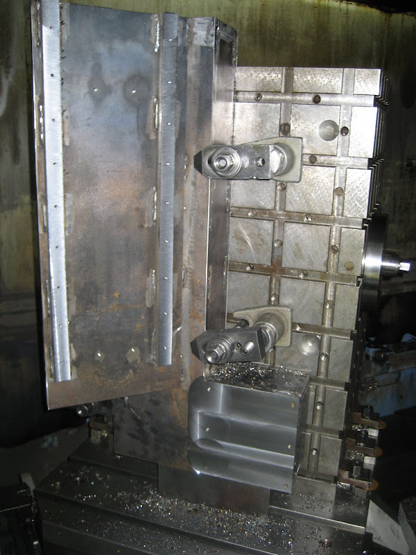
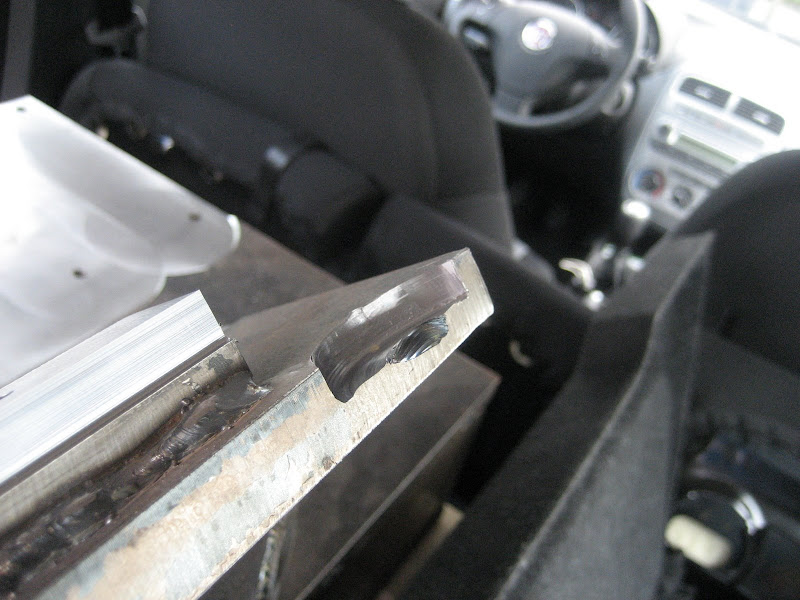
And now the best part, this gonna make me feel a little better when I makes mistakes in the future. The machinist with 16 years of experience with this machine managed to ramp the face mill right into the workpiece. Its not ment for ramping so the material in the center is more or less just "pushed" away. Some serious forces, the machines is rated 380v 87amps!
From KX3
-
05-29-2009, 10:43 PM #243
Community Moderator


- Join Date
- Mar 2004
- Posts
- 1661
The difference is that it will now take another 16 years before he makes that mistake again.

Looks very good.
-
05-30-2009, 05:36 AM #244
Registered
- Join Date
- Sep 2008
- Posts
- 86
I've been following this since you started this thread. You are doing great work and I am impressed by your persistence. I'm looking forward to your further progress.
-
05-30-2009, 10:20 AM #245
Gold Member
- Join Date
- Aug 2006
- Posts
- 1602
Very nice work

Were those setups done on the machine, or were they done with the fixture and lathe-bed horizontal on a bench, and then just hoisted on to the machine?
I'm glad you got it home safely - from those pics , an E-stop in your car could have left you with a lathe bed for a head!
-
05-30-2009, 02:19 PM #246
Registered
- Join Date
- Feb 2006
- Posts
- 1187
A lil bondo will fix that screw up. Its looking great so far, love your enclosure.
-
05-30-2009, 04:29 PM #247
Member
- Join Date
- Sep 2006
- Posts
- 6463
Er, Guldberg, was that a counterbore he decided to give you for free or as they used to say in UK when someone made a mistake at the start, "a false start" LOL.
You could always just drill a hole through the centre of the "cutout" and bolt something to it.
It's in the right position to hang a light on.
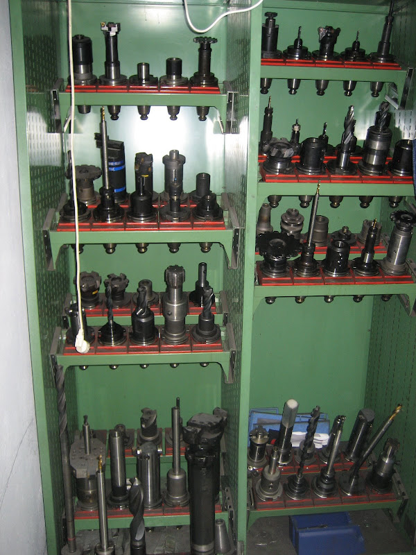
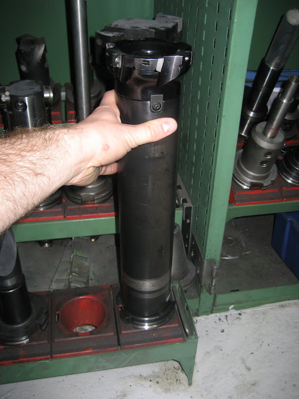
I love that tool cabinet with all the "goodies" hangin there, I bet you've got one in mind for yourself too.
Ian.
-
05-31-2009, 12:47 PM #248
Registered
- Join Date
- May 2006
- Posts
- 573
Thx guys.
The machine has interchanging pallets, so the pallet just roll outside the machine where you can access it. We decided to add a eye bolt (?) to the end so we could lift it with the crane in the second setup. With both the drill and the tap already in the machine it only took like a minute anyway. Got to get me one of these one day:-)
I did a quick mount of the rails and the x-axis carriage. We made cut along the rail stand off's, so it was a breeze to dial in the rails. Wont be long till both axis are running, so I have to start fabricating the headstock soon

From KX3
-
05-31-2009, 06:16 PM #249
Registered
- Join Date
- Nov 2004
- Posts
- 284
Great job designing and building your CNC Lathe. Can't wait to see this machine in action. Keep of the good work.
Willy
-
06-01-2009, 05:44 AM #250
Registered
- Join Date
- Apr 2007
- Posts
- 90
Hi,
Good progress, whats the spec of the motor. What is the approx weight of the machine with motors, tool changer with Chuck. I think for the solid machine you are building a lot of strength on the base is required if machining mild steel at good speeds. What do you think can be the cut depth that you can go in MS ? . I have seen many lathe builds but not as professional as yours, love to start one bases on your designfor my personal use ASAP.
-
06-01-2009, 08:16 AM #251
Registered
- Join Date
- May 2006
- Posts
- 573
The motor are rated 3hp. I have no clue of the weight, but the base itself weighs approx. 90kg. My best guess is that the total weight of the machine will end up at around 300kg.
As i have not done any calculation on this, I dont know the capability of the machine yet, but I designed it to be more ridgid and with more power than similar sized lathe, so i hope that it will performe well
-
06-01-2009, 11:50 AM #252
Registered
- Join Date
- Apr 2007
- Posts
- 90
Good 300 Kgs of machine weight is enough & equal to commercial machines available in the market. i think it should not vibrate as 3 Hp motor will slice up metal without problems. Have you thought about having a Hydraulic power chuck, which would put your machine at par with the commercial machines. In India the minimum price for a CNC turning centre is around $20,000/- , i cannot invest as i have already invested for Mechmate CNC router which is 95% complete and i have orders only for small lathe jobs for which a commercial machine is not required. I am eagerly waiting for the test results from your machine to start, i am planning to start with the ATC sometime this month prior to building the machine.
-
06-04-2009, 11:38 AM #253
Registered
- Join Date
- May 2006
- Posts
- 573
I just "ordered" a piece of Ø150x250mm steel for the headstock spindle housing. Here is the basic idea, comments are very much appreciated
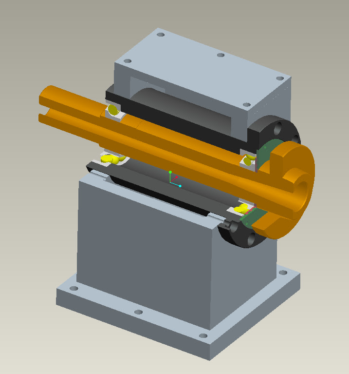
From CNC
-
06-04-2009, 12:16 PM #254
Registered
- Join Date
- Apr 2007
- Posts
- 90
Hi,
From the drawing i see that the spindle head can be removed without removing the head stock as in a commercial machine. What is the wall thickness of the spindle shaft and what is the bearing that you plan to use.
Vishnu
-
06-04-2009, 02:25 PM #255
Registered
- Join Date
- May 2006
- Posts
- 573
Its a commercial spindle i bought as a spare-part, they are used in the smaller Optimum lathes. The wall thickness is 9.5mm. The bearings are SKF 7209BEY bearings, bought on ebay
-
06-04-2009, 03:55 PM #256
Member
- Join Date
- Sep 2006
- Posts
- 6463
Hi Guldberg, can't say I would go a bundle on the bearing configuration.
Having angular contacts at each end is not the best way to go.
It is better to have two angular contacts at the front, back to back, and two sealed radial at the drive end spaced apart a bit, to take the pull from the drive belt(s).
The bearing layout as shown is prone to move when any heat from running makes the spindle expand longitudenally.
I know this is heresy, but you "could" remachine the spindle housing bearing bores quite easily to achieve this configuration, without undergoing major redesign problems.
In the spindle end I would go to an ER40 collet set-up as opposed to the morse taper, if manual work change is desired, as well as the chuck mount, alternatively an air collet closer would be great, possibly with 5C collets or whatever, up to about 30mm capacity or so.
I would also arrange for a vertical toothed belt drive down to a reduction pulley, to prevent belt sideways pull affecting the spindle, and then out sideways to the VFD motor to maintain low speed torque without loading the VFD too much.
This setup was used by Mike.......(can't think of his surname), to build the CNC lathe bought by Rube in the USA, when Mike decided to build a Horizontal Borer from scratch.
Ian.
-
06-04-2009, 04:42 PM #257
Gold Member
- Join Date
- May 2005
- Posts
- 2502
Guldberg, not sure what your commercial spindle spare part is or how much you have invested in it, but I have some off the wall thoughts for you:
- Have always liked building the spindle around a particular collet configuration the way Hardinge has. I think I would go for 16C if the scale of the lathe allows. If not, then 5C. There is a huge amount of inexpensive (and expensive) tooling out there around these standards. This may be less true in Europe though, I don't know.
- Re the bearings, Ian has it right about where to put the angular contacts. For a lathe, I am fascinated by the idea though of not using ball bearings or rollers either. There are endless threads talking about the accuracy and surface finish for bronze bearings being better. You line bore them in place on the lathe for even greater accuracy.
The problem with them is they will be severely rpm limited unless you use a pressurized oil system, in which case you wind up with a nice hydrostatic suspension on the oil film. This is a proven design as it's what cars use for their crankshafts. Automobile oil pumps are very cheaply available. I warned you it was off the wall, but it would be fascinating to try!
Now you'll want a blown hemi to drive your spindle if you choose this route...

Cheers,
BW
-
06-04-2009, 04:44 PM #258
Registered
- Join Date
- Mar 2006
- Posts
- 357
 That would be "Steve" :wave:This setup was used by Mike.......(can't think of his surname), to build the CNC lathe bought by Rube in the USA, when Mike decided to build a Horizontal Borer from scratch.
Ian.
That was my early setup and one I probably should have stayed with.
-
06-04-2009, 05:19 PM #259
Member
- Join Date
- Sep 2006
- Posts
- 6463
Bang on old sport, Steve it is, it all comes back to me.
Yeah, the hydrostatic bearing using a bronze bush with a diam/length ratio of about 3 :1 will certainly be extremely accurate as long as you supply oil under pressure, as in a car engine.
When I was apprenticed in the mid 50's we had a Churchill crankshaft grinder, for regrinding Caterpillar D8 crankshafts, and to increase the output they invested in another machine of German manufacture.
As usual the manual was the last thing to be consulted and on start up the grinding wheel spun for about 10 minutes while the slides were powered back and forth etc.
All of a sudden there was a screech from the belt drive and the wheel seized up solid.
After about five minutes it freed up and was re-started, but the same happened.
After consulting the manual it was discovered that a mixture of SAE50 motor oil mixed with diesel fuel in ratio of 50:50 was the recomended head bearing lubricant.
The straight motor oil was too thick for the hydrostatic bearing which rapidly overheated.
The hydrostatic bearing consisted simply of a long bronze bearing of about 200mm (9") diam and a metre (3ft) long.
The bearing was split in two seperate halves longitudinally, and a small hydraulic cylinder maintained the two halves under pressure against the oil mix pressure being pumped to the bronze bearing.
As long as the oil pressure is kept up, the spindle will run on the oil film without metal to metal contact.
It takes a bit of accurate machining to produce good results, but in my humble opinion, the angular contact ball bearing set-up is easier to produce and makes for a firmer spindle support under load without deflection.
Ian.
-
06-04-2009, 08:34 PM #260
Registered
- Join Date
- Mar 2006
- Posts
- 357

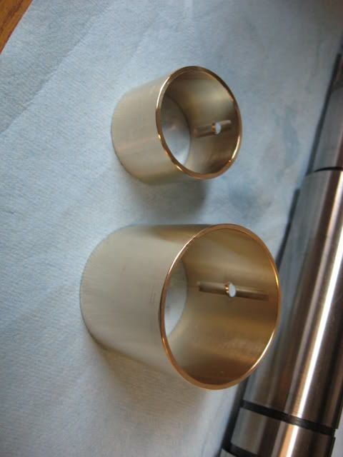
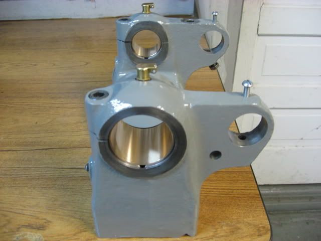
The plain bearing is a remarkably simple and extremely accurate way to go. I machined my own bronze shells for my SB9A. The original cast iron bearing surfaces were trashed when I took possession of the lathe. I did a quasi line bore to the headstock to remove enough material to fit new bronze shells. I converted it to a top oiler- total loss system which means constant fresh clean oil. I reworked the oil drainback grooves in the headstock for better return flow so it would not spit any oil at speed and it runs super clean.
I did not split the bronze shells and instead relied on the split headstock to crush/distort and provide the needed LEMON shape of the bronze shells for proper control of oil "whirl" and "whip". My bestest .00005" indicator shows almost no movement of spindle runout. I run it at about .0007" clearance.
I recently removed the spindle and after 1year of use the bearing shells looked EXACTLY as when I first machined them. I could not see any wear whatsoever and not even any markings of any sort . Astonishing!
The spindle will run at 1500rpm and just be warm. It's just a little old southbend flatbelt, but it sure does give a nice surface finish.
I'm a big fan of plain bearings and a pressurized system would be really neat!
Steve

 Reply With Quote
Similar Threads
-
CNC lathe scratch build!
By aarongough in forum Vertical Mill, Lathe Project LogReplies: 37Last Post: 02-07-2013, 10:06 PM -
Looking for Specs for a scratch built lathe
By breathe in forum Vertical Mill, Lathe Project LogReplies: 18Last Post: 06-16-2011, 12:56 PM -
From scratch. Lathe, Mill, or maybe both.
By MrBean in forum Vertical Mill, Lathe Project LogReplies: 27Last Post: 10-28-2010, 01:25 PM -
CNC Lathe from Scratch
By mackeym in forum Vertical Mill, Lathe Project LogReplies: 85Last Post: 06-02-2010, 12:20 AM
