


This is a project I have been working on for about half a year now. Well the planning started allmost a year ago, but the machining started fall 07. Right now the lathe is at my work, and I havnt been able to take pictures of it yet (lazy and I keep forgetting my camera).
The lathe is made up of mostly aluminium. It has linear rails on all axis, and ball screws with zero backlash. I have spent way too much money on it so far, but I have also recieved a lot of funding for it. It can do 80IPM rapids (limited by TurboCNC) and it has a max spindle speed of about 3500rpm.
I had to take the ATC home for some soldering and I figured I could take some pictures of it. So now I have uploaded them and here they are.
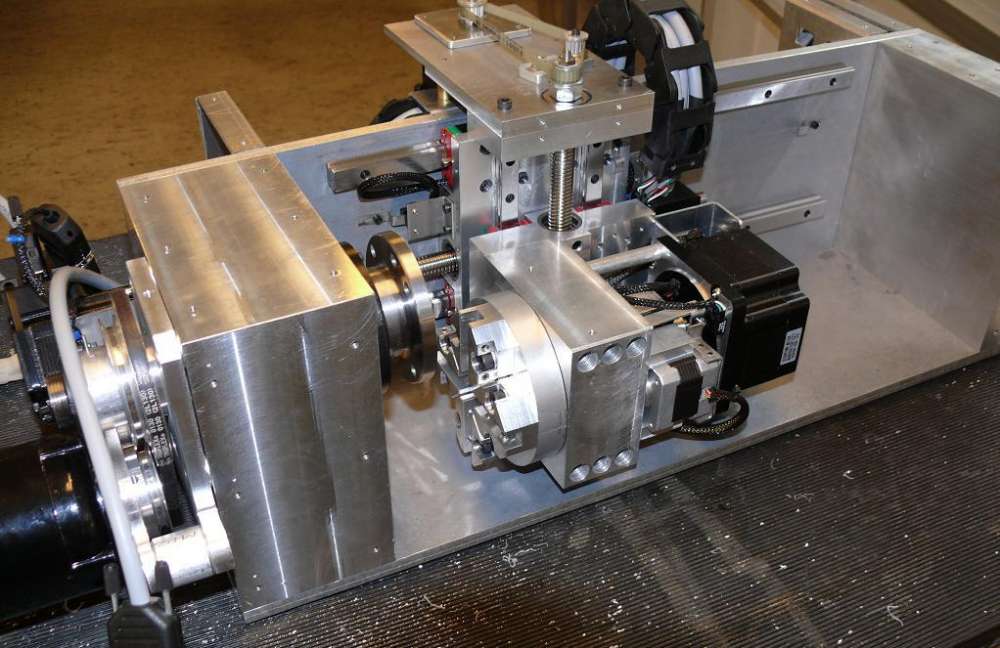
It's controlled by a single PIC. I can set the controller in a calibration mode where I can control the ATC through a simple keyboard to jog it into the first position and to calibrate the locking pin. The ATC has 2 sensors so that it knows where it's starting position is. I'm using TurboCNC for all my machines, and TCNC sends out a single pulse for toolchange. So when the ATC recieves a pulse, it will switch to the next position. When it's done moving, it sends a handshake signal back to TCNC to tell it that it's ready.
The ATC is locked down with a single spring loaded tapered pin. I was a bit worried if this was enough, but after taking 3mm cuts in brass it seems to be quite tough. I have also tried to use a 2mm cutoff tool, and there are some vibrations, but it does the job nicely.
The whole thing is made from aluminum, and it has 2 tapered roller bearings. The ATC is bolted down with 6 M6 bolts. It has 2 stepper motors. One 56oz-in, and one 425oz-in stepper motor. I chose such a big motor to have enough torque at the outer diameter (it's 100mm in diameter). I'm still not sure if it's enough, but time will tell. I started out with a rubber ring between the rotating part and the body of the ATC, but there was just too much friction. So I switched it out for a plastic ring with springs to press it against the body.
I will post more pictures when I get them. I don't know how often I will update this topic, but when I have something, I will try to post it.
PS. the photos are uploaded in the photo section under Home Made CNC Machines. So if you want to see bigger versions, just head over there.
Thread: Blight's CNC lathe
Results 1 to 20 of 79
-
04-16-2008, 10:59 PM #1
 Registered
- Join Date
- Sep 2006
- Posts
- 607
Blight's CNC lathe
-
06-18-2008, 11:09 PM #2
Registered
- Join Date
- Sep 2006
- Posts
- 607
I finally got around to take some pictures of the machine. All the covers have been removed because I was installing the limit switches and some connectors.
Here are some pictures of the lathe seen from various angles.

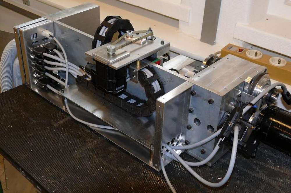
I have also taken some pictures of the waycover for the X axis. I first started out with a rubber cover, but then I thought "if I'm going to be making this, I'm gonna make it right". So I went with this telescopic waycover design.


Finally there is one picture of the modules I have made for my controller box. Every card, driver, controller..etc has it's own mounting "box" with connectors. This makes it easier for me if I want to change something or add something.

-
06-19-2008, 03:42 AM #3
Registered
- Join Date
- Sep 2004
- Posts
- 145
MAN!
That is absolutely gorgeous!
Please keep posting pics
MarkInsanity "doing the same thing and expecting a different result"
Mark
www.mcoates.com
-
06-19-2008, 05:20 AM #4
Registered
- Join Date
- Aug 2005
- Posts
- 132
Wow what a great job you've done on it.
Very nice work
Rod
-
06-19-2008, 06:55 AM #5
Registered
- Join Date
- Dec 2006
- Posts
- 118
Simply amazing work!!
I don't give a damn if you don't like me, cause i don't like you cause you are not like me.
-
06-19-2008, 08:53 AM #6
Registered
- Join Date
- May 2006
- Posts
- 573
Awsome. Looks like you like soldering :-D
Defenitly have to see this in real life someday. Where do you get your aluminium at? Work? That is my one and only concern, i cant seem to find a supplier for aluminium, unless im willing to pay alumeco for full length rod, bars etc.
-
06-19-2008, 01:07 PM #7
Gold Member
- Join Date
- Aug 2006
- Posts
- 1602
Wow, that looks amazing! What does the second stepper on the tool-changer do - unlock the mechanism?
I really like your way-covers, if you don't mind me asking, how did you attatch the scissors mechanism to the cover sections?
-
06-19-2008, 06:16 PM #8
Registered
- Join Date
- Sep 2006
- Posts
- 607
Guldberg: Well with a total of 2000+ solderings (for both the lathe and mill), I don't really have a choice :P
I get all the aluminium at work and at school. The machines (well the lathes do) we have at work leave a fair amount of raw stock unused (for clamping). Most of the time they wont mind if I take some. This is only for round material though. Because I work at a workshop that deals with prototypes and such, we have a lot of bits and pieces lying around that I can use for this project.
If you want to order small quantities of metal, you can order it from metallstore.de (germany). They also have lots of linear rails, ballscrews and profiles. Thats where I ordered the rails and screws from.
Digits: Yes it locks the mechanism. It's directly driving a spring loaded screw with a tapered end. I had to make a tiny thrust bearing (just took the balls from a ball bearing and made some grooves) to minimize friction. I also have a optical sensor for referance position on it along with one on the rotor too. When you power up the machine, the stepper motors are not locked entierly in place. They first settle in after a few steps. Because of this I have had to program a startup sequence for the ATC which jogs it back and forth a bit before finding its referance position.
I attached the scissor mechanism to the cover by a brass spacer and a screw with a setscrew comming in from the side to lock the other screw in place.. If that makes sense. The scissor mechanism is connected with pop rivets in the corners. I actually made two of these mechanisms, but found out that there was only space enough for one, so I have one as a backup. Don't think I will ever have to change it.
I might make some kind of seal for the cover to keep chips from getting jammed in between. I have not had a problem with this, but I can see it comming.
Oh and one more thing. I have ordered fuse holders, some more connectors and cable glands. So those ugly holes where the cables go through will be covered a bit up, and there will be less chance of damaging the cable. I placed this order 2 months ago at a place called "brincks elektronik". Well I asked them to order some stuff from Elfa (big electronics supplier) for me. Every time I came and asked for the order, they had a new excuse. First it was that it was delayed. Second time elfa did not have what I wanted in stock (when I placed the order, they had everything). Third time the guy at brinck told me that elfa had delivery problems (This one I actually never believed). And when I came there about a week ago, he hold me that they had never ordered it because the store was changind owner. Was kind of pissed at that time. Now I have ordered all the stuff to my home add. in Norway (elfa can ship to private customers in Norway, but not it Denmark. I think I'm to blame for this, because you could do so through the norwegian site before. And so I did, and the next time you could not do that. First order was almost $2000 of just cables and connectors).
Sorry for the long posts. I tend to get carried away.
-
06-19-2008, 06:46 PM #9
Registered
- Join Date
- Nov 2005
- Posts
- 655
wow, I mean WOW!
Great work on your build.
Keep up the great work,
JackWalking is highly over-rated
-
06-19-2008, 10:05 PM #10
Registered
- Join Date
- Sep 2006
- Posts
- 607
PPS. Thanks guys!
-
06-20-2008, 10:40 AM #11
Gold Member
- Join Date
- Aug 2006
- Posts
- 1602
So, have you got countersunk screws going through the cover sections and into the brass-spacers, and in which case, how thick is the sheet metal you're using? Originally Posted by The Blight

I doubt you'll get many chips inbetween the sections as your folding looks fantactically accurate, but unless you add wipers, isn't there a danger you'll get coolant dragged underneath as they compress?
I'm glad it's not just me who spent a fortune on cables and connectors - they really do add up, but I am very, very impressed by just how modular your electronics is.
Cheers.
-
06-20-2008, 02:36 PM #12
Registered
- Join Date
- Sep 2006
- Posts
- 607
Ah yeah forgot to mention that. You got it right. I'm using 2mm sheets.
I don't use coolant on this machine. I'm thinking of making a small tank with something similar to mineral spirits for working with aluminum, but thats about it. I don't know how much steel I will be working with, but if I one day start to work with steel, I will just add another tank containing cutting oil. I have some tiny fluid pumps that I'm going to be using. If I'm going to make this, it's going to be one line for each tool. I think the cutting fluid will come through the centre of the tool changer (through the shaft).
I have spent a total of $4500 on electronics. This is for both machines (including drivers, but not stepping motors). I could have bought 2 ready made systems, but that would not be fun. And having them both shipped to Denmark would cost quite a bit. It would also cost a lot in taxes and custom.
-
06-20-2008, 03:32 PM #13
Registered
- Join Date
- May 2006
- Posts
- 573
You are talking about a mill also, do you have pictures of it also?
-
06-20-2008, 08:37 PM #14
Registered
- Join Date
- Sep 2006
- Posts
- 607
It's just an X2, so nothing special. It has ball screws on all axis and it has 0 backlash as far as I can measure. I have spent a lot of time cleaning and adjusting it to make it perfect, so there is no slop either. I also have an ATC for it on the drawingboard. It's a 6 station tool turret mounted on the head of the mill. Will post a picture of the drawing at some point.
Will take a picture of it too at some point. It's sitting right next to our couch in our living room. (bor på kollegie). I'm also working on a PCB mill made from aluminium extrusions. I'm thinking of a way to make it more rigid, so I have to go to the hardware store tomorrow.
-
09-18-2008, 05:47 PM #15
Registered
- Join Date
- Sep 2006
- Posts
- 607
Okey the Lathe is just about done. Missing a few things in the controller box (relay control and the ATC controller along with a "missing step checker"), and I have a couple problems that I have to figure out. I added a steel bar to the top of the back sheet which hold the Z axis linear rails to make it more rigid. I measured deflection at the rails to about 0.2mm which is too much. So after adding the steel bar to the back, I measured deflection to 0.01mm, and 0.06mm at the tool tip with about 40kg pressure on it. Tried to use the parting tool (2mm) on brass, and there are no vibrations.
One problem that I just can't figure out is the spindle index pulse. In TurboCNC you only need one pulse per rotation, and so I have a optical sensor hooked up to the breakout board. The problem is that I get an error (when running the spindle at 600rpm or less) saying that the spindle is moving faster then 5000rpm, or you can hear the Z axis stepping motor changing speed while thread cutting. This indicates that the index pulse needs a bit cleaning. The thing is that I'm running the index pulse through my digispeed XL card, which squares the pulse up. I put a scope (digital) on the thing today, and the pulses look nice and clean both before and after cleaning. Still TCNC turn up these weird problems. I'm starting to think that it might be a problem with the parallel port on my computer (not a laptop). I have 2 ports on it. One is on the mobo, and the other is a PCI card. Right now the index pulse runs through the PCI card, so I will try the other one tomorrow. If that doesn't work, then I don't know what to do. I wonder how short spikes there can be on the index line before it has any effect on the software.
Other then that, there is not much room left in the controller box now. Should have made it larger (wider), but I got to live with what I have. Will have to take some more pictures soon. I have started on the table for the lathe, and I have added carrying handles. I can lift it by myself, but it's hard to move it around.
One other thing that's worth mentioning is that I have started working on a bar feeder for the lathe. I have been drawing several types of collet closers for the lathe, and I might just end up making my own collet system. My problems it to find enough steel for it. I might be so lucky as to get some old collets ranging from 0.5 to 20mm.
I also found out that drill chucks take up too much of the Z axis to be any good, so I will have to make my own drill bit holders. Might be some brass inserts that I drill a hole into (drill bit in the spinlde, to get perfect alignment), or some other system. Might switch out the sheet way cover with one that takes up less space to get closer to the spindle, so that I can use MT3 collets for the bar feeder. This would give me 65mm more travel to work with. Still wont use drill chucks though..
Might take some pictures next week.
-
09-18-2008, 06:12 PM #16
Registered
- Join Date
- May 2006
- Posts
- 573
Pictures and videos please:-)
-
09-19-2008, 12:22 AM #17
Gold Member
- Join Date
- Apr 2006
- Posts
- 3498
Really amazing...What a neatness..what a proffessional look..What a design...Wow
 ..Keep up posting and can you post pics of drawing (2D/3D)... a CNC lathe is in my list...and I will follow ur design...
-
09-19-2008, 02:13 AM #18
Registered
- Join Date
- Feb 2006
- Posts
- 1187
Dude! What are you doing? Now you have set the bar so high, I don't think anyone else can top it!! Awesome work, keep it up!!!!!!!!!!!!!
-
09-19-2008, 05:48 PM #19
Registered
- Join Date
- Sep 2006
- Posts
- 607
Thanks guys!
Didn't really do anything on the lathe today. Just some documentation on wiring. Figured out where I want to put the ATC controller and some other control circuits. I hope that I get the time to take some pictures and maybe a video next week.
Also found out which collet system I'm going to use. Cant remember what it's called, but it's one that schaublin made.
-
09-27-2008, 11:22 PM #20
Registered
- Join Date
- Sep 2006
- Posts
- 607
Got to 2nd parallel port to work yesterday. Just had to set it up right, and it seems to be working now, but I would like a couple more inputs for some of the other features I want to add.
I have stared working on a controller for the toolchanger and MPG too.
I also found out that I can't use the collet system I had settled on, so now I'm set on making my own set. I would like a maximum through diameter of 15mm, so that's what I'm aiming at. The collet closer should be fairly easy to build. Getting the material on the other hand is harder. I need enough steel for 20 collets that are 50mm long. 1100mm should do. Might get some of this at my school.
Next week I will take some pictures of the lathe. Maybe even a video of it. Who knows how lazy I will be.


 Reply With Quote
Similar Threads
-
Converting my Engine Lathe to an 8-Station Turret Lathe!
By widgitmaster in forum Uncategorised MetalWorking MachinesReplies: 95Last Post: 08-09-2018, 04:56 PM -
What's the different between a CNC Swiss Lathe and a regular CNC lathe?
By squale in forum Uncategorised MetalWorking MachinesReplies: 3Last Post: 11-09-2007, 04:54 PM -
Lathe Comparison - Best small lathe for CNC
By acondit in forum Mini LatheReplies: 48Last Post: 03-24-2006, 02:10 AM -
Anyone have a mini cnc lathe or medium sized cnc lathe
By nymachinist in forum Mini LatheReplies: 6Last Post: 01-24-2006, 03:36 AM -
New Micro lathe built by me (my second lathe)
By Stevie in forum Uncategorised MetalWorking MachinesReplies: 15Last Post: 11-03-2004, 10:56 AM
