


SJH,
Love the pictures- nice work on the components. I did a simple DC motor conversion using a treadmill motor on a machine. Keeping the motors cool at low speed was a concern since they do not have a fan. I found a 125V AC computer style fan at Surplus center and mounted it right on the end of the motor using the motor bolts and a simple adaptor plate. I wired the fan to the 125V on-off switch that went to the DC controller. I used a double pole double throw toggle on-off-on switch on the DC out put to the motor so I could reverse it. After running the motor, I can leave the 125Volt switch in the on position so the fan keeps running while putting the DC reversing switch in the off position so the current to the motor is stopped. That way you can cool the motor down for a few minutes after you finish.
Results 21 to 40 of 52
-
12-27-2008, 03:44 PM #21
 Registered
- Join Date
- Dec 2007
- Posts
- 413
-
12-29-2008, 12:34 AM #22
Registered
- Join Date
- Mar 2006
- Posts
- 357
update!
The machine is going to be cnc'd.:rainfro:
My cnc mini lathe is going to be dismantled and many of the parts used on this machine. This machine is simply superior even when used as a lathe compared to the cnc lathe I built. The beautifully built meehanite Gilman box way slide is simply much better than the steel base with linear rails I built for the mini lathe.
I'll use linear rails for the crossfeed though.
So, it'll be a cnc lathe, Horizontal boring mill and also will be capable of surface grinding small parts.
Steve
-
12-29-2008, 01:32 AM #23
Registered
- Join Date
- Jan 2007
- Posts
- 277
Werd!

-
01-10-2009, 04:26 PM #24
Registered
- Join Date
- Dec 2006
- Posts
- 839
This keeps getting better every time I look into this thread. Sure would like to find one of these box ways myself, and oh yea a planetary set!
Jess
-
01-12-2009, 09:40 PM #25
Registered
- Join Date
- Feb 2007
- Posts
- 24
Hello Steve,
wounderful machine. I can´t expect to see milling results. Incredible Gearbox.
Greetings Rene
-
01-17-2009, 10:02 PM #26
Registered
- Join Date
- Mar 2006
- Posts
- 357
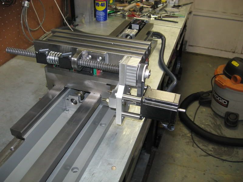
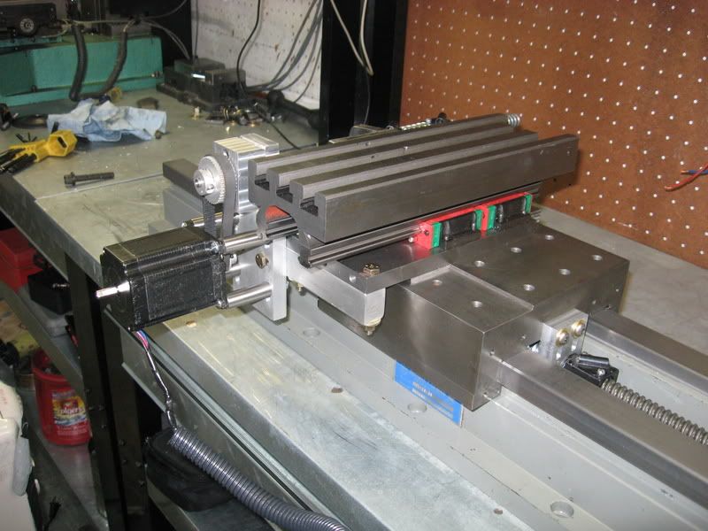
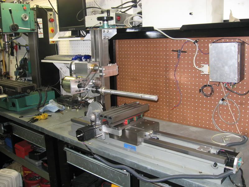
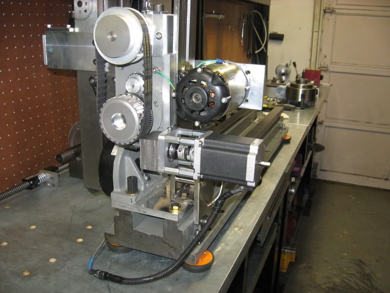
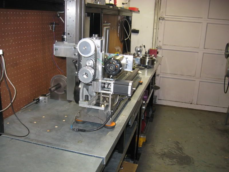
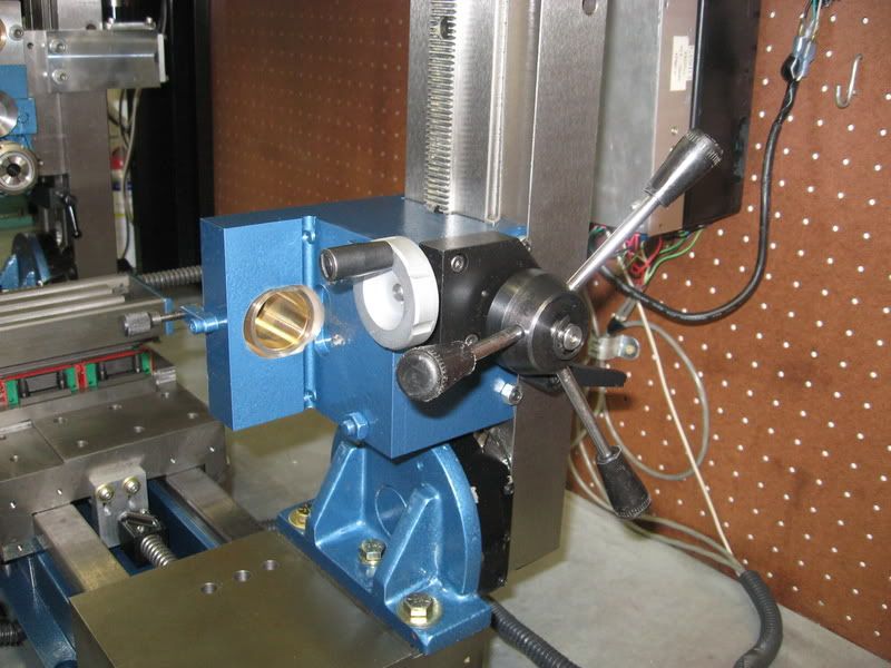
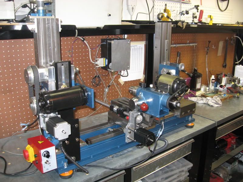
Some more progress made- It now has 3 working axis. cncd long and short axis and manual z-spindle height axis.
6.5" on the cross feed running at 200IPM,. So I'll be able to use it as a short gang slide for a few tools in lathe mode.
recap-
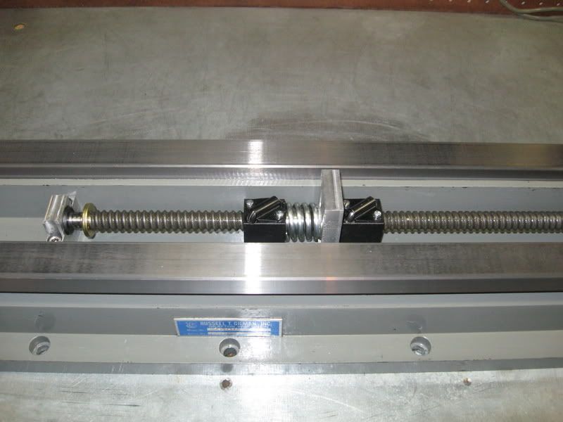
The bed and base is a high end Gilman box way slide. .ooo5" accuracy over 3 feet. Meehanite iron base with hardened and ground rails. Scraped bearing surfaces and anti friction coating on the gibs.
The 2 columns are from a Sieg mini mill. The spindle is from a Sieg mini mill retrofitted with better bearings.
The z-axis for the horizontal spindle is 16tpi acme with a delrin nut. A gas strut will be used for counterbalance.
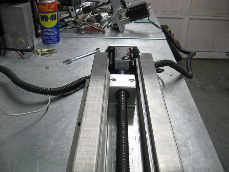
.2 pitch ball screws are used on the long and cross feed axis with dual preloaded nuts. 269oz steppers on each axis. The cross feed has been tested at a smooth reliable 200IPM and I have not yet fully tested the long axis as I just finished it today.
The cross feed table is mounted to a doweled sub plate so it can be easily removed for parts that might need to be mounted directly to the table.
The z axis is manual for now.
The spindle will be indexed with a proximity sensor and this info sent to mach 3. This will enable the machine to cut any pitch thread.
The spindle transmission is a 3 speed planetary drive with reductions of 72:1-40:1- and 13.5:1 and features a detent torque sensing clutch. A direct drive mode with slight reduction is also available by swapping the belts around.
Spindle speeds of around 20-3000+. A dc 5000 rpm motor and a Minarik DC drive will be used.
The boring bar in the pictures is there for scale. It is 1" diameter by 13" long.
The end support column can either be stationary and locked to the bed or towed with a strap by the main table.
The end column uses a rack and pinion for it's z-axis with fine feed. Heights will setup equally with a height gage.
The end column still needs to be finished.
A sliding support for the spindle will be built to give the headstock better rigidity.
I plan on adding another stepper to allow indexing the spindle and a small grinding/milling head to be used on the cross feed table.
Once finished I'll paint and pretty up the machine.
Steve
-
01-17-2009, 10:04 PM #27
Registered
- Join Date
- Mar 2006
- Posts
- 357
-
01-17-2009, 10:39 PM #28
Gold Member
- Join Date
- May 2005
- Posts
- 2502
Interesting project. You should be able to get some gang tooling on that big cross slide, which will be nice.
As long as you are CNC'ing, you should stick an encoder on that spindle motor so you can run it as a servo. That way it can index the workpiece for some live tooling to drill a bolt circle or even do some light milling.
Are you at all concerned that the forces on the headstock can knock it out of tram relative to the bed?
The rest of the machine looks rock solid. Should be a nice larger capacity replacement for your small CNC lathe.
Cheers,
BW
-
01-17-2009, 11:01 PM #29
Registered
- Join Date
- Mar 2006
- Posts
- 357
Bob,
I'm using the standard x2 mini mill column assembly for the main spindle head.
These do suffer from flex but hold their position quite well. I had a cnc'd x2 some years ago. I'm already impressed with how rigid it is without any bracing yet.
The headstock actually has much less overhang on the dovetail column compared to the vertical setup on a mini mill because of the way I mounted it. So that right there makes it more rigid.
BUT, I have plans for a big brace to lock the head on the motor side to the other side of the bed. This will greatly add rigidity. Also there will be a cross brace that ties in both z-axis dovetail columns and that should really add some extra rigidty to the entire machine.
I plan on using a stepper to position the spindle for gear cutting etc. Sort of like Evan did with his cnc 4th axis lathe head on his mill. Not as high tech as a servo spindle but pretty much the same end results.
The spindle will be indexed to mach3 for threading and speed control and then the stepper takes over for position indexing.
I have not worked out the details yet though. This build is a semi budget build. I'm trying to use what I have on hand as much as possible.
I won't rule out technical improvements in the future as the budget allows.
Steve
-
01-18-2009, 02:11 AM #30
Gold Member
- Join Date
- May 2005
- Posts
- 2502
Sounds good.
I was having a discussion with some fellows a little while back about doing spindle indexing as you describe with a dual motor config. The main concern was to provide some sort of an arrangement to ground the stepper coils when it was not in use so the Back EMF wouldn't annoy the Geckodrive. The stepper will be a little generator if its spinning while the main motor is going.
It gets to be six of one half a dozen of the other when you're thinking about 2 motors versus a servo. I still haven't decided on my own lathe which way will be better.
Cheers,
BW
-
01-18-2009, 03:15 AM #31
Registered
- Join Date
- Mar 2006
- Posts
- 357
Bob,
Good points.
But I'm just a hobbiest so everything does not have to be 100% automated for me. So the plan is I will just program in pauses or stops when switching between lathe and index positioning and/or continuous 4th axis mode. I won't have the stepper turning when not in use for the reasons you brought up. I'll activate the stepper drive only when needed, manually by some sort of mechanical arrangement.
Steve
-
01-18-2009, 01:16 PM #32
Registered
- Join Date
- Dec 2006
- Posts
- 839
This machine just keeps getting better. I can just amagin the surface finish this puppy will put out when doing lathe or horizontal opps. I have got to build one.
Jess
-
02-02-2009, 09:19 PM #33
Registered
- Join Date
- Mar 2006
- Posts
- 357
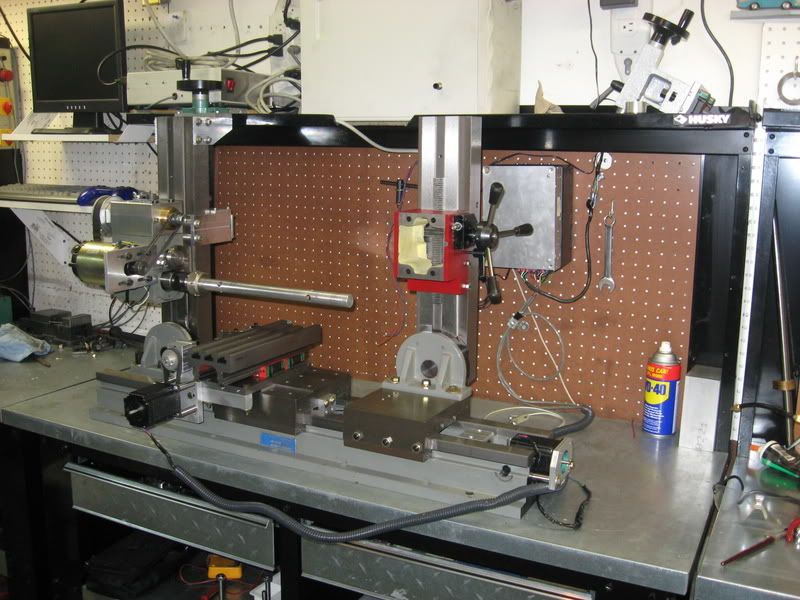
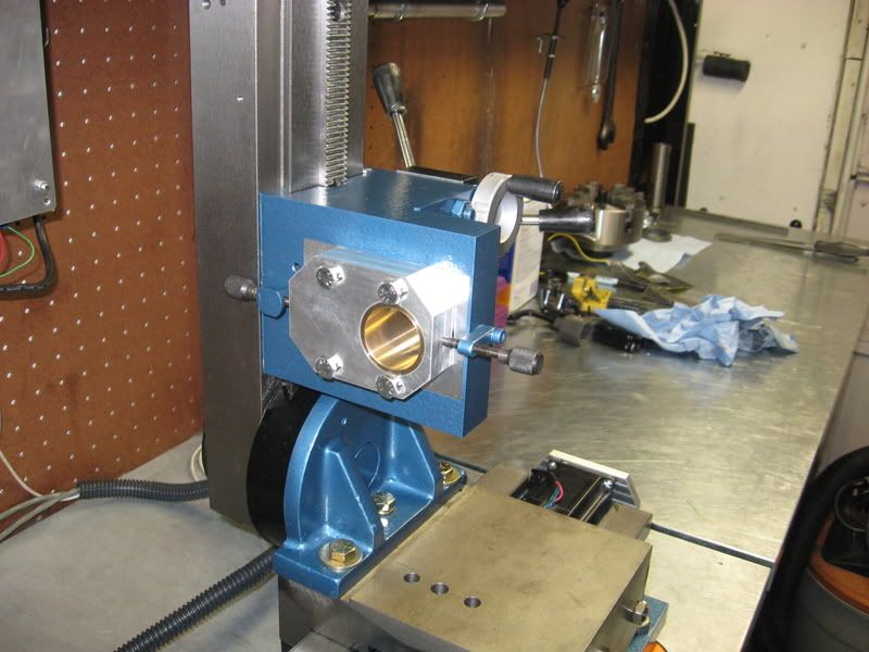
some updates,
Better column mount with secondary brace greatly reduces spindle deflection.
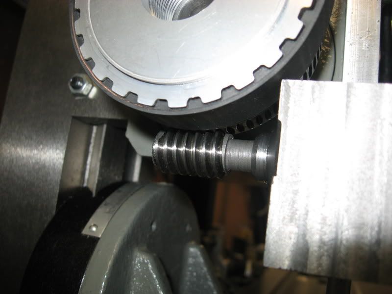
I finished building the spindle indexing system and tested it out.
It works fantastic. As for now I have a strong 425oz motor on it so i can run pretty tight backlash.
An external gear was added to the drive system. An Iron block with a precision bore is mounted to the headstock. Inside the bore is fitted an eccentric shaft keyed which itself is bored to accept the worm gear which provides the bearing surface.
To engage the drive you grab the stepper and rotate it 180 degrees and because of the eccentric, the worm meshes with the ring gear. It locks into place with a ball spring detent inside the iron block. To disengage the drive, just turn the stepper 180' opposite. No tools needed, no belts to remove nothing. Works perfectly.
This was the last major hurdle. I'm now ready to begin final assembly, alignment and then bore the end column support bushings.
Steve
-
02-22-2009, 02:44 AM #34
Registered
- Join Date
- Mar 2006
- Posts
- 357
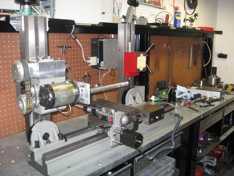
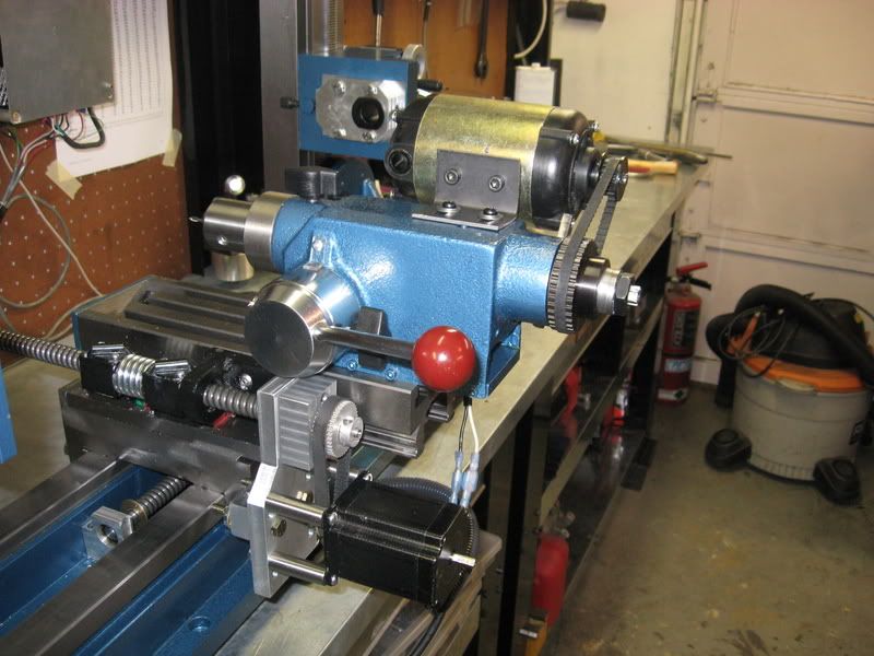
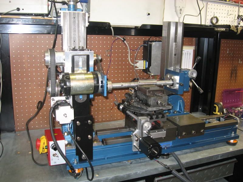
 It's alive!
She is just about finished. It was dismantled, cleaned, painted and the spindle and axis's very carefully aligned.
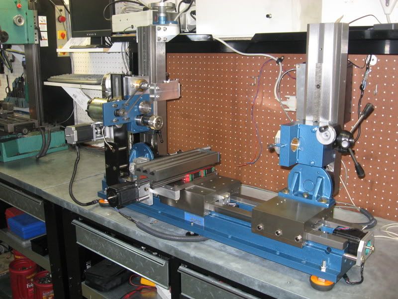
The end column support is finished. It has plenty of adjustments to tweak in a line bar, arbor or work piece.
The master bushing is 1.25" ID. Removable reducers will be made for various sized boring bars, arbors etc.
I hooked up a spindle sensor to MACH3 and now have the true rpm readings for each gear ratio.
The highest ratio is 65:1 with a range of 0- 75 rpm
2nd gear is 40:1 with a speed range of 0-125rpm
3rd gear is 12:5 with a speed range of 0 400rpm
4th gear which bypasses the planetary transmisson is 1.7:1 and a max speed of 2900 rpm.
It's a pretty good broad rpm range.
I tested the machine for several hours today. The first impression you get is that it is very quiet , just a high pitch from the motor. The planetary transmission adds almost no extra noise compared to direct belt drive.The heavy duty aluminum housing and bronze bearings plus ball bearings for the shafts makes this unit one of the best working things I have ever built IMO.
It operated without fault or getting hot for a good 4 hours non stop almost in all 3 gears. It is sealed and runs in heavy oil.
The detent clutch works fantastic and saved my ass several times today during testing. There is enough torque at low speed that without the clutch to save it, this machine would BREAK something.
The little mini lathe dc motor powering the spindle through the planetary transmission has plenty of power. The machine has no problem taking a .050" DOC in 303 stainless and easily takes a .1" DOC in 6061.
I have a even more powerful motor I may add though.
I'll be testing out it's horizontal cutting action with a boring bar and arbor type cutter next.
So here is a video of it making it's very frst chips in some 303 stainless and 6061 aluminum.
This is just a clip of it doing a few lathe ops and it's poor quality, but you can at least see and hear the machine at work.

Steve
-
02-22-2009, 12:56 PM #35
Registered
- Join Date
- Sep 2006
- Posts
- 607
That is one of the most versatile machines I have ever seen! It's a work of art!
-
02-22-2009, 02:25 PM #36
Gold Member
- Join Date
- Jun 2004
- Posts
- 6618
I concur. Very cool. I would get some better way and screw covers on there though.

It seems a pity to cover some of it up. It looks so nice. How about some clear covers? Lee
Lee
-
02-22-2009, 04:17 PM #37
Gold Member
- Join Date
- Sep 2006
- Posts
- 1738
Yea, make some clear lexan covers!
-Jason
-
02-22-2009, 05:05 PM #38
Registered
- Join Date
- Mar 2006
- Posts
- 357

Thanks guys,
I just used that piece of accordion tube for the cross feed screw as a temporary protection measure. It will be replaced with something more suitable and not so f-ugly.
The z-axis screw unless using a line boring bar with the cutter located way back, is always out of the way and needs no cover at all.
Steve
-
03-01-2009, 09:29 PM #39
Registered
- Join Date
- Mar 2006
- Posts
- 357
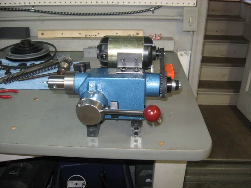
I just finished this project. It is of course a small drilling and milling head with a rack and pinion quill. The motor is from a mini lathe.
The housing was taken from an old cheap import drill press. I cut it down and boxed it in. Then indicated the quill dead level and flycut the mounting surface.
It originally had a mt2 tapered spindle.
I made a new spindle out of some 1144 stress proof. It is a 3/8" end mill holder type spindle.
The spindle has 1 bearing at each end of the quill cartridge and I added a bearing preload nut. The splined drive has 2 bearings.
Steve
-
03-01-2009, 09:31 PM #40
Registered
- Join Date
- Mar 2006
- Posts
- 357
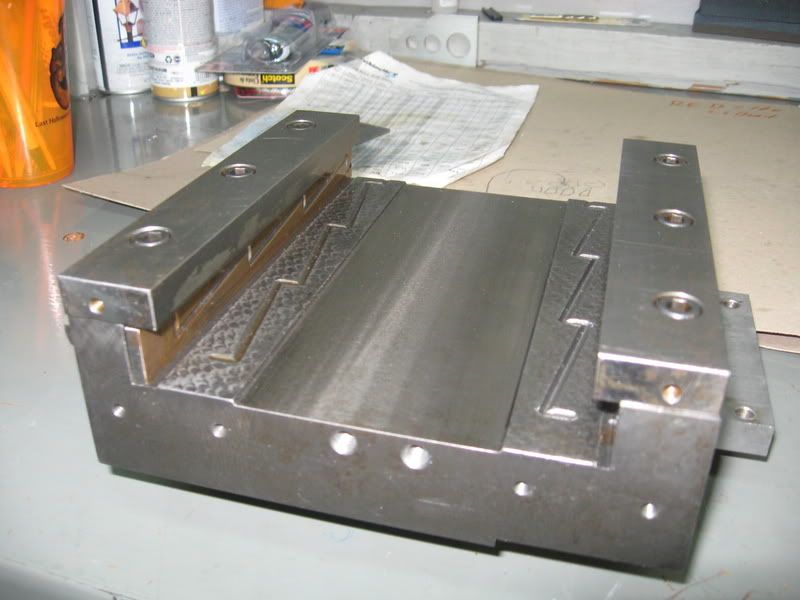
Also, tried out a simple line boring op. The machine makes it so easy!
Here is a boring bar reducer sleeve. It's made of delrin.
And a pic of a simple line boring setup on some pipe.
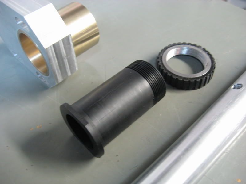
Steve

 Reply With Quote
Similar Threads
-
horizontal cnc boring machine?
By bp092 in forum Commercial CNC Wood RoutersReplies: 1Last Post: 10-25-2007, 03:51 AM -
Machinist - Horizontal / Vertical boring mill operators
By quinnj in forum Employment OpportunityReplies: 0Last Post: 10-18-2007, 05:26 PM -
Horizontal and Vertical boring mill operators
By quinnj in forum Employment OpportunityReplies: 0Last Post: 10-16-2007, 07:58 PM -
Horizontal Boring
By harryn in forum K2CNCReplies: 9Last Post: 06-30-2007, 05:37 AM -
New Photos! Horizontal Boring Mill (30HP)
By mzartop6 in forum CamSoft ProductsReplies: 1Last Post: 09-12-2006, 02:11 AM
