


Hi all,
I started my machine up this morning and ran into a problem that I can't seem to solve. I have a smaller Mitsui Seiki (apx 27" travel in X) vertical CNC machine with a Fanuc 6M controller.
I began my morning starting it up the same way as always. As I started homing out the axis, I did Z first which went to 0 just fine. Then I switched to Y and when I hit the Jog+ button Z actually went up and overtravelled instead of Y moving. When it overtravelled the Z axis jumped back down just below the limit switch. I got a 434 Z Axis alarm on the screen which I could not clear. So I powered down the machine and keep getting the 434 alarm when the machine tries to power up. Here is a play by play in pictures of what is happening.
(For some reason the pics aren't showing up in the thread so here is a link to each one too)
The machine first gets the power turned on and I get my usual NOT READY screen.
http://www.barchdesigns.com/cnczone/434/1.jpg
I push my PRP button to power on the servos....
http://www.barchdesigns.com/cnczone/434/2.jpg
And the 434 alarm shows up as long as I am holding the PRP button in
http://www.barchdesigns.com/cnczone/434/3.jpg
When I let the PRP button go the alarm goes away.....the alarm only shows when the machine is trying to power the servos up
http://www.barchdesigns.com/cnczone/434/4.jpg
I checked the servo boards in the back...looks good, green lights
http://www.barchdesigns.com/cnczone/434/5.jpg
...and checked the breaker as the note suggested by some previous owner..
http://www.barchdesigns.com/cnczone/434/6.jpg
....it wasn't tripped and looked ok. I forced it to trip and reset it a couple times just to make sure.
http://www.barchdesigns.com/cnczone/434/7.jpg
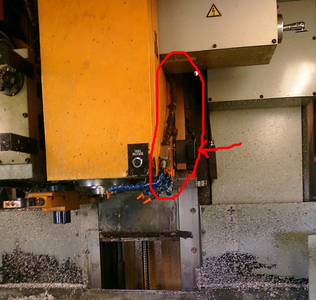
This is how the machine sits now (I know it is a tight fit to the ceiling). I tried moving the ball screw by hand to try and lower Z to see if that would fix the problem. There must be some kind of brake on it cause it won't budge at all by hand with the machine powered on or off.
http://www.barchdesigns.com/cnczone/434/8.jpg
A few things I have tried already:
Since there is no longer a 4th axis on this machine (removed when I bought it over a year ago) and the Z and 4th axis boards in the back of the machine are the exact same, I swapped them with one another. It didn't change anything upon power up. Still get the 434 alarm and no new alarms.
I also checked to see if parameters got messed up, but they all seem to be set OK. I didn't go through one by one, but picked quite a few random ones and compared with my backup and all were the same that i checked.
The Z axis limit roller switch is not on the metal tang at the top, so Z is not at it's limit. There is also a proximity switch up there which I am not sure what it is for. I assume one is a hard limit and one is the Zero switch. I can get a picture if need be.
I temporarily unmounted the prox switch at the top to make sure it wasn't limiting something, and there was no change after doing that.
This one has me stumped and I need your help.
Any ideas?
Thanks,
Benjamin Barch
Barch Designs
Results 1 to 20 of 29
-
09-11-2009, 06:35 PM #1
 Registered
- Join Date
- Jul 2008
- Posts
- 156
Z Servo Axis 434 Alarm on Fanuc 6M
-
09-11-2009, 07:14 PM #2
Gold Member
- Join Date
- Jun 2008
- Posts
- 1511
You may not be on the hard switches but you may be at the softlimit settings. Do you have a OT release or bypass button on your machine? You need to hold the button and Jog or Handwheel off the limits then reset the machine.
Stevo
-
09-11-2009, 07:21 PM #3
Registered
- Join Date
- Jul 2008
- Posts
- 156
I tried that. There is an overtravel release button in the back. Even with holding that in I can't get the machine to start up to jog the axis with the jog wheel. I am at the machine all day today, so my next step is to look up the soft limit parameters and change them if needed so the machine doesn't think it is within the soft limit (if that is what it is thinking)
-
09-11-2009, 07:29 PM #4
Registered
- Join Date
- Jul 2008
- Posts
- 156
Found these parameters:
143= +X Limit
144= +Y Limit
145= +Z Limit
146= +4 Limit
433= +5 Limit
147= -X Limit
148= -Y Limit
149= -Z Limit
150= -4 Limit
434= -5 Limit
145 was at 2000 so I changed it to 99999 and it didn't affect the startup after that. Still get the 434 alarm when holding PRP. Good idea though.
-
09-11-2009, 08:30 PM #5
Registered
- Join Date
- Jul 2008
- Posts
- 156
Does anyone know for sure if the 4 boards (encoder boards I think) in picture #5 are all the same? To me the only difference is on one of the chips there is a X Y or Z but all the electronics look identical.
When I swapped the Z and 4th axis boards nothing changed....but then I got thinking I don't know if the 4th axis board was good in the first place.... The board marked Z was originally in the 4th axis spot and the Y board that I assume was originally in the 4th axis spot was in the Z place. I wonder if someone already swapped these two if there was a problem in the past...
So anyway going along that line of thinking I swapped the Y board and put it in the Z spot and something new occurs. I get a 400 alarm now. But I am not 100% sure these boards are all the same.
I wonder if I do have a encoder board that went bad...
What do you think?
-
09-11-2009, 08:48 PM #6
Community Moderator
- Join Date
- Dec 2003
- Posts
- 24221
The 434 alarm usually refers to a bad resolver on Z axis, or the board, the resolvers on a 6M go back to a system board rather than a drive.
Al.CNC, Mechatronics Integration and Custom Machine Design
“Logic will get you from A to B. Imagination will take you everywhere.”
Albert E.
-
09-11-2009, 09:03 PM #7
Registered
- Join Date
- Jul 2008
- Posts
- 156
Hey Al, Can you tell me that again in lamens terms. I know enough to get myself into trouble with the maintenance side of things on a CNC, but I am not sure what a resolver is or where it is located.
Just from what I have tried switching the 4th axis and Z axis boards with no change in the machine state, I think the boards are the same (either both working or both with the same problem), so I am leaning towards your bad resolver theory. Where is it located?
Thanks,
Benjamin
-
09-11-2009, 09:20 PM #8
Community Moderator
- Join Date
- Dec 2003
- Posts
- 24221
The resolver is inside the rear motor cover, it is usually driven by a flat gear wheel off the shaft.
It looks like a small motor with 6 leads on it, this is used on these in place of an encoder.
If you have another axis motor approximately the same size you could sub them, to see if you get a different axis error.
It could also be the board, so a motor substitute will prove it.
Al.CNC, Mechatronics Integration and Custom Machine Design
“Logic will get you from A to B. Imagination will take you everywhere.”
Albert E.
-
09-11-2009, 10:01 PM #9
Registered
- Join Date
- Jul 2008
- Posts
- 156
Al, I had a look inside the Z axis motor cover and the Y axis motor cover. They both appear to be the same resolver. Were you saying if I had a complete spare motor (which I don't) to swap those out, or to take the resolvers out of the motors and just swap the resolvers? Is that safe to do or will I mess something up by removing the resolver from the motor? The Z axis motor is bigger than the X and Y motors and I don't know if that is difficult to replace or swap a motor or if it would be safe because they are different sizes.
Here are pictures of each:
Z Axis
http://www.barchdesigns.com/cnczone/434/11.jpg
Y Axis
http://www.barchdesigns.com/cnczone/434/12.jpg
Also do you know where the motor resolver wires go to? What board do they plug into? Couldn't I swap the Z and Y resolver connectors where they plug into the board and see if that swaps the axis error?
I found this on the main board... Is the far left board the resolver board (It's marked RES/IND)? Is this where the resolver wires go to? All the connections on this board are just marked with numbers like 36, 37, 38 etc. No Axis references at all.
http://www.barchdesigns.com/cnczone/434/10.jpg
Thanks so much!
Benjamin
-
09-12-2009, 12:16 AM #10
Community Moderator
- Join Date
- Dec 2003
- Posts
- 24221
Those photo's appear to be the Tach's. If they have two wires and four brushes, that is not the resolvers.
These are resolvers, ebay item 120350841073.
RES/IND is the Resolver/Inductozyn board.
If you can identify which axis is which, you should be able to transfer swop the plugs over to see if the alrm number changes to a different axis.
IIRC, the centre digit (x) is the axis, 4x4.
Al.CNC, Mechatronics Integration and Custom Machine Design
“Logic will get you from A to B. Imagination will take you everywhere.”
Albert E.
-
09-12-2009, 05:04 PM #11
Registered
- Join Date
- Nov 2006
- Posts
- 175
as far as the motors are with tacho only, you should be lucky owner of inductosyn feedback on this machines. It is the same resolver, but straightened in a line. Look somewhere alongside guideways for a long metal scale with two wires from it and reading head - travelling plate with at least 4 wires from it. All these wires usually goes to a small box with amplifier electronics, after that to resolver/inductosyn board in the CNC.
Check for any garbage around the scales, clean with air gun the gap between the scale and reading head. Specially take care for small chips and be careful - both parts have fine windings grated on mating sides. Try to find some book in the cabinet mentioning "inductosyn" in order to find the necessary gap between head and scale. usually it is <1mm and aligned better than 0.015mm on the whole travel.
-
09-14-2009, 04:05 PM #12
Registered
- Join Date
- Jul 2008
- Posts
- 156
I think we are on the right track. I just got off the phone with Fanuc and they said they think it is either a resolver or a cable. I found the linear scale for the Y axis, but can't find it for the Z. I might have to get someone over here who knows CNC machines. Otherwise I might have this thing completely torn apart before I find what I am looking for...

I would like to lower Z to get a better look from the top (I have short ceilings). How do I release the brake on the Z Axis so that I can manually turn the ball screw and lower down Z?
-
09-14-2009, 04:22 PM #13
Community Moderator
- Join Date
- Dec 2003
- Posts
- 24221
Its probably is energized when the machine comes out of E-stop.
You may have to power it direct if it is a brake on the motor.
It could also be a separate brake on the B.S. or a hydraulic pin, etc.
The motor brake is usually at the shaft end and is a 2 pin MS connector.
Al.CNC, Mechatronics Integration and Custom Machine Design
“Logic will get you from A to B. Imagination will take you everywhere.”
Albert E.
-
09-14-2009, 05:39 PM #14
Registered
- Join Date
- Jul 2008
- Posts
- 156
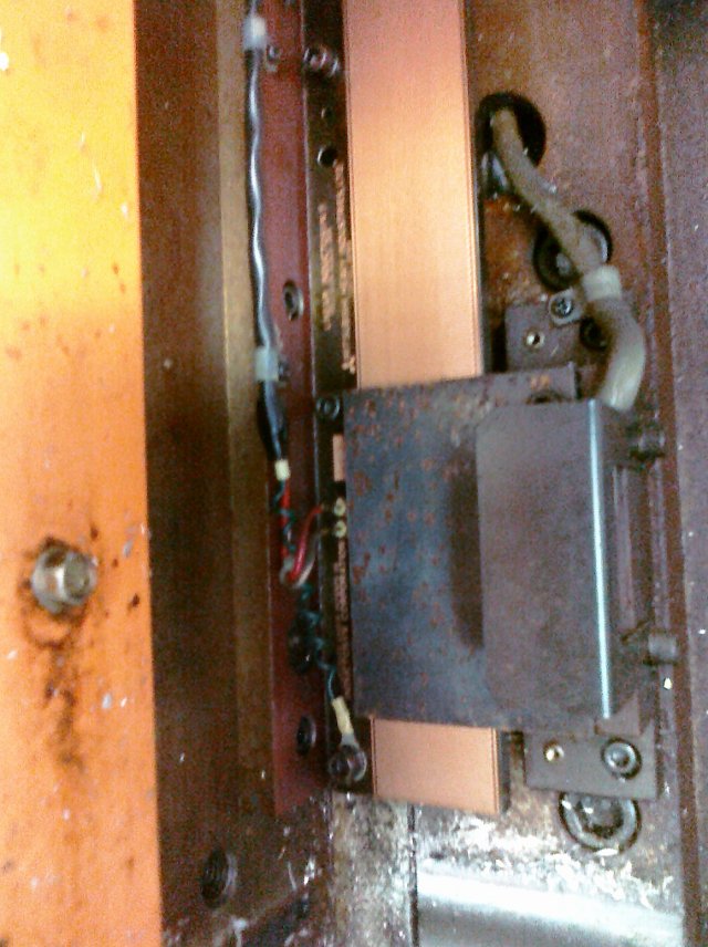
I found the linear scale for the Z axis. It was behind a shroud/cover. I blew air between the read head and the scale. It looked pretty clean, and it didn't affect the alarm after powering back up. Now I am looking for a bad or loose cable somewhere. I am not sure how to test the electronics for the amp/preamp between the read head and the inductosyn board in the CNC.
The scale has 2 wires and a ground and the read head has 4 wires. Is there a way I can meter these to see if they are working?
I have a friend coming over tonight to see what he can help with and I am waiting on a call back from a nearby CNC repair company to schedule a tech repair visit (I can feel my wallet getting lighter already...)
http://www.barchdesigns.com/cnczone/434/13.jpg
http://www.barchdesigns.com/cnczone/434/14.jpg
-
09-14-2009, 05:50 PM #15
Community Moderator
- Join Date
- Dec 2003
- Posts
- 24221
Can you not swap the X & Z plugs over on the board?
The machine is not going to move if it has a feedback error.
Al.CNC, Mechatronics Integration and Custom Machine Design
“Logic will get you from A to B. Imagination will take you everywhere.”
Albert E.
-
09-14-2009, 06:00 PM #16
Registered
- Join Date
- Jul 2008
- Posts
- 156
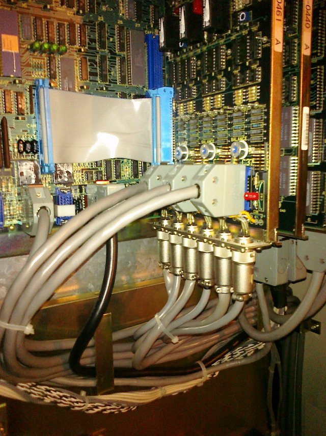
That is exactly what I want to do...however, the plugs are not labeled with Axis letters. It appears that there are 3 plugs for each axis (9 total plugs) (which corresponds to what Fanuc said....1 for command, one for speed, and 1 for external position device)
There are 6 plugs along the bottom (3 pairs) and 3 more plugs on the side of the board.
The 3 in the side are C31, C34, and C37
The 6 on the bottom are C32, C33....C35, C36....C38, C39
Do you know which corresponds to what? My RES/IND board# is A20B-0008-0461 A
http://www.barchdesigns.com/cnczone/434/15.jpg
-
09-14-2009, 07:39 PM #17
Community Moderator
- Join Date
- Dec 2003
- Posts
- 24221
I will see if I have info on that board, however I believe it is the 6 at the bottom that you have to change, and just looking at them, cable dia etc, it looks like they are in pairs, as would be expected.
Also the Honda plugs and pots above them look like they correspond to each pair.
Al.CNC, Mechatronics Integration and Custom Machine Design
“Logic will get you from A to B. Imagination will take you everywhere.”
Albert E.
-
09-14-2009, 08:17 PM #18
Community Moderator
- Join Date
- Dec 2003
- Posts
- 24221
I only have the info on the 10,11,15 etc. But they show two cables for the Inductosyn itself, one for the head and one for the scale.
According to the lettering, I would say the Z is the pair nearest the front of the card.
A quick continuity check, one end to the other should confirm it.
Al.CNC, Mechatronics Integration and Custom Machine Design
“Logic will get you from A to B. Imagination will take you everywhere.”
Albert E.
-
09-14-2009, 09:29 PM #19
Registered
- Join Date
- Jul 2008
- Posts
- 156
I swapped the cables going into the RES/IND board and the alarm changed from 434 Z to 424 Y. That means the RES/IND board is still good and the problem is either a cable, Resolver, or Preamplifier for the Resolver.
I am getting closer to knowing what the problem is, now I just need someone who is able to check out a Resolver and Preamp and tell me where the problem is. I really would not like to pay $500 for someone to come out and tell me a cable is bad though....
For future reference for others:
On the RES/IND board# A20B-0008-0461 A the connectors are:
X = C31, C32, C33
Y = C34, C35, C36
Z = C37, C38, C39
-
09-14-2009, 09:52 PM #20
Community Moderator
- Join Date
- Dec 2003
- Posts
- 24221
Fairly simple to check the continuity of a cable.
You may need to disconnect the head end as resolvers/inductosyns are fairly low resistance, or just disconnect the board end and compare the resistance between pins with Y & Z.
There are only about 4 connection per plug.
Al.CNC, Mechatronics Integration and Custom Machine Design
“Logic will get you from A to B. Imagination will take you everywhere.”
Albert E.


 Reply With Quote
Similar Threads
-
Fanuc Om-417 X Axis Servo Alarm
By intermax in forum FanucReplies: 17Last Post: 05-11-2022, 11:55 AM -
alarm 408 servo alarm "serial not RDY", αP18 fanuc mtor code
By sting007 in forum FanucReplies: 2Last Post: 09-10-2018, 09:21 PM -
NEED HEELP ALARM #414 Y AXIS SERVO ALARM?
By PICMAN in forum FanucReplies: 6Last Post: 04-29-2011, 11:20 PM -
Fanuc 6m alarm 421 & 420 Y servo
By actionman in forum FanucReplies: 5Last Post: 11-16-2006, 08:50 PM -
Fanuc 18I Z axis servo Alarm 410
By Ninus in forum FanucReplies: 3Last Post: 09-22-2006, 05:16 AM
