


Hello dudes, i have assembled a board using this schematic
http://netikka.net/maggot/bipolar.png
Here's the board layout
http://netikka.net/maggot/bipolar_brd.png
X2-1 is +5v
X2-2 is +15v
X2-3 is GND
X1-1 is DIR
X1-2 is STEP
M1-M4 are the motor outputs
However it doesn't work.
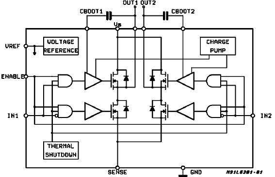
I have measured about every pin using my oscilloscope but the only strange thing i found is that the outputs of the L6203's (pin 1 and pin 3) are high all the time, when i step it slowly (using jog in Mach3) i can see some small flickering around 14-15volt, but i assume it should switch between high and low.
Since i can't find anything wierd on the board, i'm asking if anyone can spot any errors in the schematic or board layout, i have checked the board about 10 times for solder bridges or stuff like that so i don't think that's the problem.
Any ideas what to look for would be nice, since i have no idea what might be wrong with this.
If you need more info just let me know, and sorry for my bad english
Greets
// MaggoT
Results 1 to 17 of 17
-
10-06-2007, 08:06 PM #1
 Registered
- Join Date
- Sep 2007
- Posts
- 32
Problems with stepper driver (L297 and L6203)
-
10-06-2007, 09:00 PM #2
Registered

- Join Date
- Feb 2005
- Posts
- 130
I found one error... look R6 & R7 on your design
R6,R7 need to be connected to GND and sense->L6203[10]
look -> http://forum-cnc.pl/index.php?topic=55.0
-
10-06-2007, 09:48 PM #3
Registered
- Join Date
- Sep 2007
- Posts
- 32
Thanks for your help.
I have fixed the problem now but it still won't run.
Another go with the oscilloscope shows that pin 1 on both 6203's now switch between 0 and 15volts, but pin 3 switches between 0 and 5 volts i can hear a small ticking sound from the motor when im jogging but it doesn't move.
When i measure between GND and motor outputs M1-M4 i just see a blinking line at 10 volts on the oscilloscope.
-
10-07-2007, 05:23 PM #4
Registered
- Join Date
- Feb 2005
- Posts
- 130
 Originally Posted by MagooT

out1 and out2 should switch between 0 and Vs
1)
data sheet of l6203 is:
Vs Supply Voltage --> min=12V typical=36V max=48 V
its better to use higher voltage...
power supply - on AC24V trafo (DC output about 32..33V)
2)
use new L6203... and make new tests
make output current measurements... current of winding Originally Posted by MagooT
-
10-07-2007, 05:37 PM #5
Registered
- Join Date
- Sep 2007
- Posts
- 32
I just found the problem (embarassing) if you look at my schematic OUT1, BOOT1 and OUT2, BOOT2 are the wrong way around on the motor outputs, so i switched them and now it seems to work
 thanks a lot for your help.
-
10-08-2007, 08:08 PM #6
Registered
- Join Date
- Feb 2005
- Posts
- 130
do you think about... Originally Posted by MagooT
making of STEP=1/2 better?
to have equal ful step and half steps...
-
10-08-2007, 11:11 PM #7
Registered
- Join Date
- Sep 2007
- Posts
- 32
I'm sorry, i don't understand what you mean, i'm not good at reading schematics
what does it do?
-
10-09-2007, 07:45 AM #8
Registered
- Join Date
- Feb 2005
- Posts
- 130
it change Vref (=>output current) for half steps... Originally Posted by MagooT
because of this => torque of motor on full steps and half steps will be equal
because of this => half steps will be more precise
-
10-09-2007, 12:25 PM #9
Registered
- Join Date
- Sep 2007
- Posts
- 32
Ok, thanks.
Another question, i'm trying to run a small motor from a printer (don't have any other specifications for it other than "10 ohms", unfortunatley), and it get REALLY hot just after a few seconds, so i assume i must recalculate sense-resistors or something? Because the chopper isn't lowering the current at all, can anybody explain how to do this?
-
10-09-2007, 07:09 PM #10
Registered
- Join Date
- Feb 2005
- Posts
- 130
yes... Originally Posted by MagooT
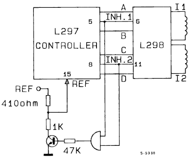
but better is to regulate Vref of L297
look there -> R23
use potentiometer (R23) to set VrefBecause the chopper isn't lowering the current at all, can anybody explain how to do this?
look on any L297/8 driver - make the same...
-
10-09-2007, 07:58 PM #11
Registered
- Join Date
- Sep 2007
- Posts
- 32
Thanks, i googled around a bit and read about vref, this is what i came up with:
Schematic: http://i20.tinypic.com/2emdkx0.png
PCB: http://i23.tinypic.com/28lg9c8.png
This allows me to adjust Vref between 0 and 1.7 volts, should work great.
Guess it's time to etch a new board an try it out
-
11-11-2008, 03:49 PM #12
Registered
- Join Date
- Jun 2008
- Posts
- 23
Hi Magoot, I made similar driver.
My 10 ohm resistor is always get to smoke because of excess heat.
Do you have this problem?
-
04-10-2009, 09:53 AM #13
Registered
- Join Date
- Jun 2007
- Posts
- 1
These are very good plans indeed. Do you have any link information ? Originally Posted by MagooT
-
08-09-2009, 04:34 PM #14
Registered
- Join Date
- Jun 2009
- Posts
- 3
Hi! i am new in electronics and i am wondering how to run my board for my cnc using the circuit with L297 and L6203.
What kind of interface do i need to put between my parallel port and the circuit board.
Thanks in advance!
George
-
01-30-2012, 12:09 AM #15
Registered
- Join Date
- Jan 2012
- Posts
- 0
Originally Posted by markcomp77
Hi Mark,
please, do you know what publication these drawings come from? It looks to me like some official ST document (similar S-XXXX numbering is used in L297/298 datasheets) but I did not succeed to find it (I've checked ST site and tried to google it few ways including search for S-9388 and S-9389 codes).
I understand the principle but I'd like to read "full story" if possible.
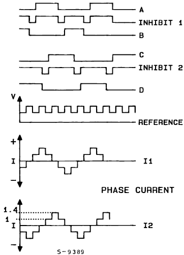
Btw. I'd say that when using simple resistor divider as VREF source it would be useful to use significantly bigger resistors in this mod compared to resistors used in VREF source (e.g. 4k1 and 10k instead of 410R and 1k) as the output impedance of VREF source will mess the 1:1.4 ratio.
Cheers, T.
-
07-17-2012, 07:46 PM #16
Registered
- Join Date
- Jan 2012
- Posts
- 0
can you support me please :)
i am glad that i linked with some one have a good knowledge in L297
i have one problem that i need to step my Bipolar stepper motor in smooth way, as a smooth rise, as i do not need to drive motor as shock pulses,
is it refer to the Chopper circuit? as i try it but the OSC with the RC components not work
and i try to sumulate it on the ISIS proteus but it could not be seen on the Digital Oscilator
please help me , i am stucked in this issue for more than 2 monthes, searching for solution on internet
-
09-07-2012, 12:35 PM #17
Registered
- Join Date
- Oct 2011
- Posts
- 0
hello sir , Originally Posted by MagooT
i googled to the same problem with L6203 and ifound your same post ,my Pin 3 is high level ,may iknow what you did exactly because ididnt understand really what you mean by you solution, how you switched it ,please ineed to know because it make me crazy my ship thank you sir

 Reply With Quote
Similar Threads
-
L298, L297 Stepper Driver
By abbe in forum Open Source Controller BoardsReplies: 23Last Post: 07-01-2012, 04:25 PM -
CONTROLADORA BIPOLAR CON EL L6203 -l297
By lupi200 in forum SpanishReplies: 13Last Post: 11-21-2011, 03:39 AM -
l297 7amp unipolar driver
By ljd10 in forum Open Source Controller BoardsReplies: 13Last Post: 10-10-2007, 01:56 AM -
L297 / L298n problems - whining motor!
By bigal in forum Stepper Motors / DrivesReplies: 2Last Post: 07-21-2005, 10:32 AM -
Troubleshooting the Simple BreakOutBoard and L297 driver
By pigifly in forum Open Source Controller BoardsReplies: 38Last Post: 11-10-2004, 09:13 PM
