


I have been working on a bipolar stepper driver and I have the mosfet / driver part done, but now I am working on the current limit portion.
I have built this circuit on a bread board with the PWM comming from a pic 18f2550 with a freq around 20khz and a 3uS on time. I think at this freq it shouldnt make any noise but I can still hear it in the motor. Not sure if its cause of the breadboard or from lack of filters...
So I am looking for any advice for adding filter circuits to my schematic.
I am using the 3uS to enable a NOR flip flop and also add dead time with the same 3uS.
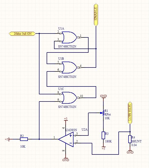
Here is the schematic.
Thread: Current limit circuit help
Results 1 to 17 of 17
-
01-19-2010, 06:40 AM #1
 Registered
- Join Date
- Nov 2006
- Posts
- 104
Current limit circuit help
-
01-20-2010, 02:18 PM #2
Registered
- Join Date
- Jan 2006
- Posts
- 738
Hi,
Looking at your circuit design.
1. Any time your 3us pulse is high your enable will be high and your motor current will not control the enable line.
2. Any time your motor current passes the threshold set by the pot, your enable goes low, if your 3us pulse clock line is also low.
Is this what you intended?
Steve
-
01-20-2010, 03:13 PM #3
Registered
- Join Date
- Nov 2006
- Posts
- 104
The LM393 goes low when the current it higher then the set point.
The 3uS pulse sets the flip flop (enable on), and this stays set untill the reset sees a high signal (enable off).
This high signal comes when both lines on U1C are low (the clock is low after the pulse so its just waiting for the comparitor).
The 3uS is also used to keep the enable on for the 3uS period as a blanking period by giving U1C a high.
I think I got that right...
-
01-20-2010, 03:32 PM #4
Member
- Join Date
- Jun 2007
- Posts
- 3757
 cycle skipping
The lower frequency you hear will be due to 'cycle skipping'
An inductor, by nature resists a change in current.
When you turn off the drive the inductor current falls, but may last much longer than you think.
So the next cycle, there is still current, and no current is commanded.
This is why we us high voltage to drive steppers so we can force the current to change in a shorter period of time, and hence run at higher frequencies.Super X3. 3600rpm. Sheridan 6"x24" Lathe + more. Three ways to fix things: The right way, the other way, and maybe your way, which is possibly a faster wrong way.
-
01-20-2010, 03:45 PM #5
Registered
- Join Date
- Jul 2008
- Posts
- 411
You also need to look at the decay paths which release the stored energy in the motor coils. You dont say which driver chips you are using but different products handle different decay paths, 'fast decay' offloads the energy back into the power rail, sometimes by part reverse driving the coil earlier. Slow decay just leaves it to decay through the L/R constant and the reverse diodes in the MOSFETS. These modes and the switching between them can greatly change the characteristics of the driver as will the L/R constant of the motor.
If you're in Europe why not come and visit the UK CNC Community at http://www.mycncuk.com
-
01-20-2010, 06:42 PM #6
Registered
- Join Date
- Nov 2006
- Posts
- 104
Well right now I am just testing the motor with 5 volts and a constant coil on (no motion on the motor) so the low voltage may cause the slow decay. I will be running the driver with my 48 volt supply when I know it works.
I am using the IR2102 driver.
-
01-21-2010, 02:36 PM #7
Registered
- Join Date
- Jan 2006
- Posts
- 738
Attached is a scope trace of the voltage across an inductor with a 14ms 10V pulse applied. There is also a resistor in series with the inductor that is about 1 1/2 times the DC resistance of the coil. The 0 V is at 2 divisions below the top of the screen. You can see the voltage jumps to the applied voltage and then decays over time to about 4 volts at which point the inductor is acting as a pure resistance. When the pulse ends, you can see the negative pulse (caused by the rapid collapse of the field in the coil) that goes to about -25V. The current at that point trough the coil is opposite of the direction of the original applied current. The larger the inductance, the larger this negative spike will be. This is the basis for creating high voltage pulses in ignition coils in cars and in stun guns.
Sound.... is created when something is moving. A speaker cone is one example. The magnetic field in a motor can actually cause the frame (and core) of the motor to deform, or bend, very slightly. This minute movement will generate sound. There is also the rotor of the motor that is free to turn and has inertia. When forced into a specific radial positon by a magnetic field (as in a stepper) there is also and opposite force placed on the frame of the motor. That is, if the rotor is accelerating clockwise, the frame will be accelerated counter clockwise. Even an AC motor operating on very clean sine wave current will generate noise (a little hum) and if you run that motor on a VFD (which uses a higher frequency PWM) you will most likely hear the "whine" generated.
Hope I didn't get too far off subject...
Steve
-
01-21-2010, 05:01 PM #8
Registered
- Join Date
- Jul 2008
- Posts
- 411
Another example of a trace...
If you're in Europe why not come and visit the UK CNC Community at http://www.mycncuk.com
-
01-22-2010, 04:48 AM #9
Gold Member
- Join Date
- Mar 2003
- Posts
- 2839
My comments: Ground referenced short-circuit detection is simple but it doesn't address the most common kind of drive fault; a short from a motor output to ground. That requires high-side (sensing +Vsupply current) short-circuit detection.
Mariss
-
01-22-2010, 03:15 PM #10
Registered
- Join Date
- Nov 2006
- Posts
- 104
High side would be nice, but I really don't know how to go about conditioning the high voltage signal to something that can be read reliably without getting some expensive purpose built chips...
-
01-22-2010, 03:17 PM #11
Registered
- Join Date
- Nov 2006
- Posts
- 104
I think I am going to try to use fast decay mode too.
-
01-22-2010, 04:45 PM #12
Registered
- Join Date
- Jul 2008
- Posts
- 411
Same way as the low side... series resistor, a low pass filter and a comparator... but vref for the comparator relative to the high side rail and well decoupled... need to use an opamp/comparator with a high common-mode voltage rating, or run the opamp off the high side rail and a ground offset. Something like the diagram... Originally Posted by fahque99
 If you're in Europe why not come and visit the UK CNC Community at http://www.mycncuk.com
-
01-23-2010, 12:27 AM #13
Registered
- Join Date
- Nov 2006
- Posts
- 104
So with using the 12volt negative regulator would that work with any high voltage then? And would it work with the same comparitor that I am using now?
-
01-23-2010, 12:45 AM #14
Registered
- Join Date
- Nov 2006
- Posts
- 104
And can you recommend a regulator for that schematic? All the ones I looked at seem to have a max input around 24-30 volts and I want to run 48 - 80.
-
01-23-2010, 02:13 AM #15
Registered
- Join Date
- Nov 2006
- Posts
- 104
I think that I could easly use fast decay by adding a XNOR gate on my hi lo inputs on the gate drivers. This should switch the polarity to the coils. Does this sound right?
-
01-23-2010, 08:14 PM #16
Registered
- Join Date
- Jul 2008
- Posts
- 411
I was assuming that 12v would be a sensible supply voltage for an opamp/comparator. You will have to decide. What are you running the existing LM393 on? Originally Posted by fahque99
If the inout voltage is too high then you will need to reduce it... The might not be easy with the range of supply volts you require. A 12v reg would need about 14v input minimum, and 24v max... thats a 10v dynamic range, and you have 32v or more.... One option might be to use a switching buck regulator rather than a linear regulator. See here for some ideas...If you're in Europe why not come and visit the UK CNC Community at http://www.mycncuk.com
-
01-24-2010, 07:44 AM #17
Registered
- Join Date
- Nov 2006
- Posts
- 104
Well I just ordered a coolrunner II kit and some 32 and 64 cell chips to replace the 74HC chips that I have been playing with. I never realized how cheap the coolrunners are.

 Reply With Quote
Similar Threads
-
I found the contradiction of the PWM method constant current circuit.
By apollonono in forum Stepper Motors / DrivesReplies: 1Last Post: 05-03-2009, 06:45 AM -
Original UHU current limit question
By chrugel in forum UHU Servo ControllersReplies: 0Last Post: 02-18-2009, 07:15 PM -
Simple Current Limiting Chopper Circuit???
By fairorgan in forum Stepper Motors / DrivesReplies: 1Last Post: 01-20-2007, 06:06 PM -
need high current regulator circuit
By tekno in forum CNC Machine Related ElectronicsReplies: 38Last Post: 05-23-2006, 02:00 AM -
limit switches circuit?
By Bryscnc in forum Mach Software (ArtSoft software)Replies: 1Last Post: 02-11-2005, 04:18 AM
