

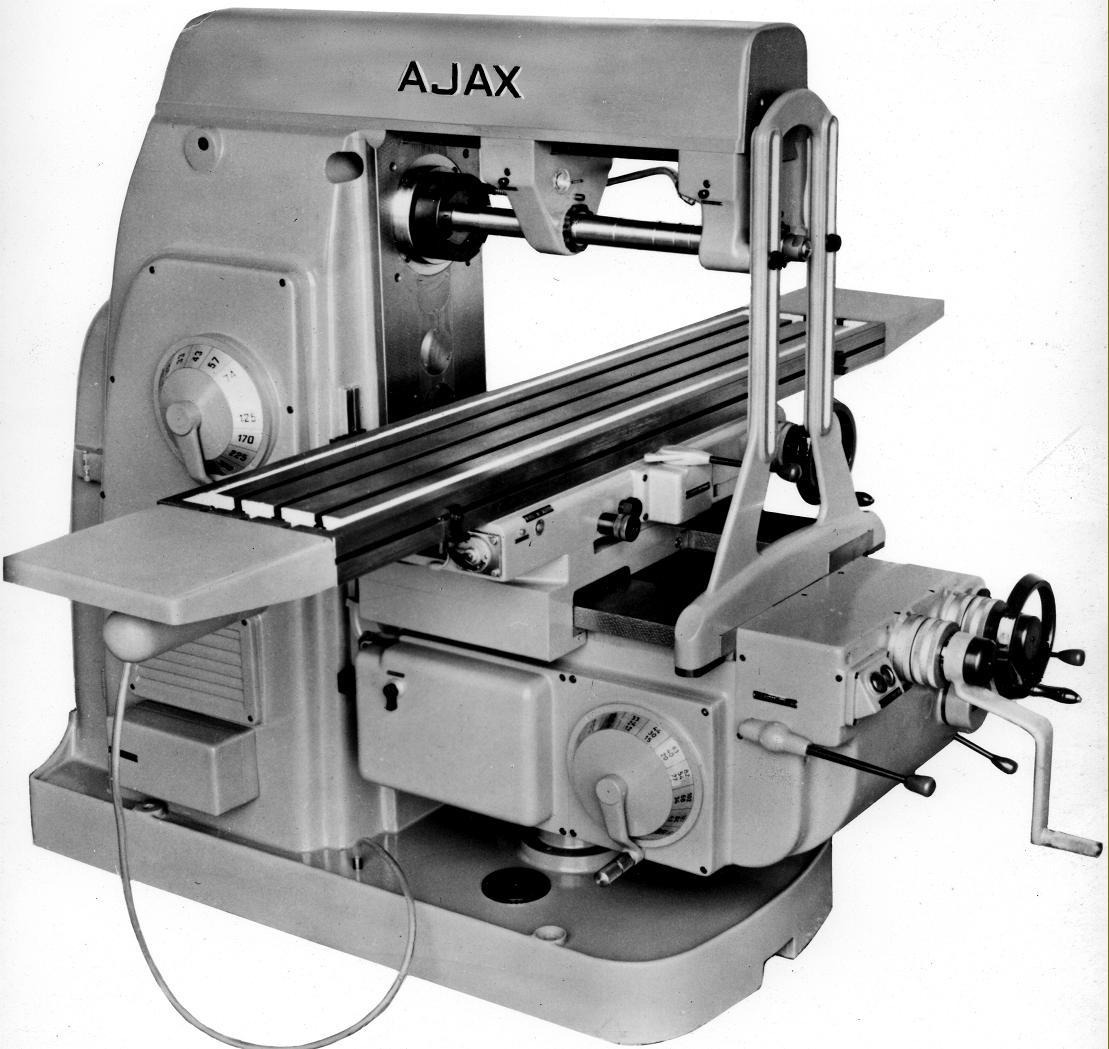
Hi all, I've inherited a CNC router fixer-upper which has almost immediately transformed into a ground-up rebuild, and spending half the day twiddling with a giant pile of poor decisions is starting to give me a lot of dumb fundamental questions I can't readily find clear answers to. For one, on open-frame machines why is the spindle almost universally hanging off one side of the gantry, with the Y axis rails and drive components arranged vertically somewhere off to one side, rather than laid out on either side of the spindle (as pictured)?
It seems like a poor layout for stability, but I see it even on big heavy industrial machines with tens to hundreds of thousands of dollars sunk into making everything as rigid and supported as possible. Just a tradeoff for ease of access/saving a few inches? Something I'm missing that makes the latter structurally undesirable?
Thread: Frame Design and Support
Results 1 to 8 of 8
-
06-03-2025, 08:32 PM #1

- Join Date
- Jun 2025
- Posts
- 5
Frame Design and Support
-
06-04-2025, 08:31 AM #2
Member
- Join Date
- Jul 2018
- Posts
- 6841
Re: Frame Design and Support
Hi Secrets - to work thru you Q's
1) The proposed arrangement does exist in some machines. The "conventional" arrangement is not universal just common
2) Having rail foundations on opposite sides of a part means that its two milling operations to machine the lands. This takes extra time and care to make the lands parallel and square. Also if the Z axis is split into two parts you may create a redundant load path and then the loads will not be shared equally leading to early failure of some bearings
3) The conventional arrangement allows the lands to be machined in one set up so they are accurate and economic to do ()if you don't machine the lands they will not be parallel and level and the cars will wear quickly()
4) machine rigidity is a design issue more then a arrangement issue ie the conventional arrangement can be made stiff enough for the application
5) if your designing a machine feel free to use the proposed arrangement and see how it goes. The saddle area of a design is complex and can be frustrating for bolt access, trying to keep the axis small, trying to be stiff.
6) I have found having the rails on top to be best and have the saddle be a 90deg angle affair. This allows access to all bolts, its very stiff and clean.
Its all a big juggle and you need to work thru all the issues to get a good solution. I have spent 100's of hours on saddles over the years! Probably 1000's Peter https://www.facebook.com/10005729791...54768154700179
https://www.facebook.com/10005729791...73356714360884
-
06-04-2025, 03:44 PM #3
- Join Date
- Jun 2025
- Posts
- 5
Re: Frame Design and Support
Thank you! I'm trying to figure out if there's a way I can build a frame suitable for milling hardware (and possibly molds?) without ready recourse to things like big machined iron castings, as that's really the area I'm lacking in. Increasingly inclining towards the suspicion I'd be better off just pulling the servos and slap em on a rusty bridgeport from craigslist, but that's no fun so anything that can plausibly cut down on deflection on a design I could fabricate from a bunch of steel channel goes a long way. Rails on top of a saddle, and probably moving the X axis up there and sucking up some awkwardness in accessing the bed, seemed like a decent starting point.
-
06-04-2025, 04:53 PM #4
- Join Date
- Jun 2025
- Posts
- 5
Re: Frame Design and Support
The actual design I was thinking about, assuming this is legible to anyone else, looks like this from the top, with the spindle and z-axis rails/screw assembly(in blue) sandwiched between the Y rails (here running on some C3x6, which I'd have to get an auto shop or something to grind) and the Y leadscrew positioned directly over one of the Y rails
-
06-04-2025, 10:00 PM #5
Member
- Join Date
- Jul 2018
- Posts
- 6841
Re: Frame Design and Support
Hi Secrets - What material do you want to make moulds from? If steel, you are talking about a mill and then you are in a different world to a router. If I'm seeing right you have a twin gantry with the Z running thru the middle? This is done on some large machines. The quickest way to the solution is to find a commercial machine that does what you need to do and study it to figure out why its like it is then move on from there. The other big question is what accuracy do you need or expect? The answer to this will drive lots of details and cost. If your idea is a twin gantry you have to be careful with how your "structural loops" work. A structural loop is where the load travels in the structure. Also called a loadpath. Its called a loop because ideally local loads stay in local loops and don't travel through lots of bits to get to reaction points. The twin gantry design with bearings on different parts and the drive nut on a different part to the load side means the loadpath is complex and long. Loadpaths should be as short as possible as this is the most rigid path. If a load can travel through different paths then it is difficult to design the elements to an optimum resolve as you can't say where the load actually is. The machine does not have to be cast iron, it can be steel or aluminium or concrete. Need to know what you are trying to do, the size of the machine and what resources you have to help further. Unless you are building large square parts then the gantry design is not needed and a mill like attached becomes attractive. Peter
Materials I've attached a space frame mill from steel as an idea. I make plywood and aluminium machines that cut aluminium easily. Ply is stiff and damp and easy to work. About to try milling steel on one of my machines to see what happens. I've played with concrete and mineral epoxy too. My production machines are steel sheet-metal and they have proven to be very good over the years. So again depends on what you need. If you need massive material removal rates contract to a big mill... I'm just polishing a new design so I attached it here for your info....There's over 400 hrs work in this design so far, so you have a long haul to go. Peter
the mori attched is my preferred config for a mill or small router. Fixed bed, mechanicals are up out of the muck and the Z is really long. Its a big mill by the way 550x550x500mm.
-
06-05-2025, 02:12 AM #6
- Join Date
- Jun 2025
- Posts
- 5
Re: Frame Design and Support
Yeah the thought chain in the original post was kicked off while watching a big stone-grinding machine with a spindle sticking way out the side of a mile-long gantry suspended between two tracks absolutely devour a slab of granite held in place by a couple vacuum pads and realizing I don't know anything about what makes a machine cut well that I thought I knew. I'd gotten familiar with the idea of anything that can accurately process anything harder than wood and end up with a decent surface needing to look like this but if that isn't true I'd like to figure out what I can get away with.
I referred to what I'm working on as a router because what I've started with was someone's homebrew quarter-sheet wood router they'd given up on; once I did some basic stuff like welding up the frame it performed adequately at that job for a little while, then lit itself on fire and died (I'll buy a lot of stuff from China but I'm never letting one of their power supplies on my property again). I had space and budget set aside to replace it but now that I'm actually in a position to do so I'm reassessing what I actually need a machine for, which falls into two separate niches:
1. Optimistically, fabrication of steel and aluminum tooling and hardware. Molds for brass casting, maybe cutter heads, custom hinges and pulls, I forget what they call them but the roller stamps the guy with the giant Victorian-era rolling mill uses to make egg and dart molding. A reasonably useful minimum working area would be something on the order of 10"x10"1.5", but as is probably always the case the more I can get without seriously compromising finish quality the better. I currently have zero capacity to do this to any real degree of precision, nor does anyone else I'm regularly in contact with, machine shops out here don't really want to deal with any of us unless we've got $20k of work for them and I think I could pretty readily get enough small-run contracts from other woodworkers and restorers looking to replace parts that haven't been manufactured in a century to just buy machine #2 in short order. Your mill looks pretty close to what I had in mind, getting a big ol Z axis like that would be great for when I wanna get weird with a design.
2. Another bigger open-framed wood router; capable of doing deep cuts on hardwoods, and maybe still some aluminum or brass, to as high-quality a surface as possible, because if I have to spend all day sanding a bunch of raggedy toolmarks or fixing where it tore out a weird bit of interlocked grain I'm worse off than before. Ideally with room to eventually give it a fourth or fifth axis to do complex high relief carvings, although afaict the software to really exploit that is still kinda cost-prohibitive. I work pretty big, while I could probably piece a lot of stuff together from ~3'x3' components I'd prefer not to. I'm way more confident in my ability to swing this one but it's more of a nice-to-have, I can and do just do this kind of work the old-fashioned way but getting a decent laser in the shop was pretty transformative, any time I can get an assistant I don't have to buy health insurance for to work while I work that's a definite upgrade.
I have, I think, a passable amount of resources I can throw at the problem for a small shop - 10'x10'x10' of concrete pad, a couple thousand bucks (and maybe a bit more if it'll make a big difference in the end result), a well-stocked woodshop sporadically choked with a million balusters or whatever, a stick welder I'm pretty sloppy with and an oxy rig I'm not, some sketchy but functional heat treating capacity for smaller parts, the ability to sit around factories pondering someone's stone CNC if not a real grasp of the math behind stuff like loadpaths. Not enough to just drop a Haas machining center in the back of the shop and call it a day or buy a Shopbot new, hopefully enough to make a hideous but functional knockoff.
-
06-05-2025, 03:03 AM #7
Member
- Join Date
- Jul 2018
- Posts
- 6841
Re: Frame Design and Support
Hi Secrets - Well a mill that can cut steel for a first time machine builder is a big project. Lots to learn, about lots of stuff.
A router to cut aluminium/brass however is doable with some coaching. The forum is ideal for that. If you float an idea it will be shot down quick sticks if its a bad idea. If the thread is quiet then its probably a goer. Steel machining requires a slow speed spindle and these tend to be servos with pulleys etc. High speed AC spindles 24k rpm units are too fast. (friction due to surface speed of tool just destroys the tool) Maybe at 12k and coated tools and good coolant they can work. I'm about to experiment down that path soon. But 24k spindles cut AL really well.
I suggest you write down your ideal spec for the machine and work that up to a realistic level. Then you can move forward with that as a reference. Lots of people dive in and spend 100's of hrs on CAD and every week their goal posts change so they burn up lots of time. Better off really nailing down what you want so the design process is more linear to the target.
Forget the "I'll build a 3 axis machine then upgrade it to 4 or 5 later" if you need a 5 axis machine then it needs to be designed from the start. If you need a rotary then it needs to be integrated into the design from the start as well. There's too many variables and unknowns in a 3 axis upgrade, usually a frustrating and incomplete process.
I do suggest you think about a plywood machine for the first one. There are examples in the forum of ply machines making AL parts that then make an AL machine. Machines make machines and once thru the first learner machine you can move on in confidence. Ply allows easy and quick adjustments or alterations... and at the end of the day that may be all that's needed. My workhorse machine is made from MDF and that cuts AL & brass easily... I'm about to design a ply machine like the Mori M1 at benchtop size, I've built several gantry and high wall designs so its time for a change... cheers Peter
By the way if your serious with cutting steel the best approach is to buy a used mill CNC or manual. If manual convert to CNC. That will be your fastest and cheapest option. You may have to wait a while for the mill to turn up but then you have the machine at that point. A hobby level mill is an expensive exercise and it will have no resale value. If you converted an old mill I'm sure you would get something back for it if that was needed. Good luck & enjoy the journey Oh and I just saw the $2k remark. Your way, way behind the starting line with 2k for the machine you are discussing...
-
06-05-2025, 04:06 AM #8
- Join Date
- Jun 2025
- Posts
- 5
Re: Frame Design and Support
Getting an old manual mill and converting it was the fallback plan, and there are people selling very impressive looking ones out here regularly for, well, a bit more than I'd budgeted but not so much I'll be ruined if it fails to make a buck; I just enjoy thinking about design a lot more than thinking about paying riggers to move a 2-ton machine over the stretch of mud between the driveway and the pad, so wanted to test the waters on whether just scratchbuilding an equally competent one had gotten more plausible while I wasn't looking.
I'll probably circle back on the wood machine again just to try out daffy configurations shortly after I look into the mill conversion further; the first one came out functional enough before the garbage components did it in, and it wouldn't be the first time I went way out of my way to get a tool exactly how I wanted it. Last time I went through Gingery's books I got about as far as the foundry that's supposed to make the lathe that makes the mill but you never know, especially if I can rope someone with more free time into doing the slow tedious parts. Thanks for all your feedback!

 Reply With Quote
Similar Threads
-
CNC Frame Design - Looking for feedback
By Thunza in forum DIY CNC Router Table MachinesReplies: 3Last Post: 08-10-2023, 02:35 AM -
frame design
By ratixx in forum AlphacamReplies: 3Last Post: 12-16-2021, 02:03 AM -
Aluminium Frame and Support Units
By ttjarrett in forum Australia, New Zealand Club HouseReplies: 1Last Post: 11-11-2011, 03:36 AM -
Urgent-Frame(bed) Design
By koolraj09 in forum Drilling- and Milling MachinesReplies: 3Last Post: 05-14-2011, 02:16 PM -
Max length for an acme threaded rod. End support or fully support the frame?
By dlpaul in forum DIY CNC Router Table MachinesReplies: 7Last Post: 03-12-2011, 09:54 PM
