


I noticed that there is a trend to build bigger and bigger CNC's and that sometimes in machines with leadscrews at around 36" and longer the leadscrew sometimes whips when spun fast.
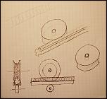
1. My first thought was, build it backwards. That's to say, fix the leadscrew and spin the nut. No whip!. The following drawing shows a hollow shaft supported by two bearings, spaced apart and locked in place with a nut. At the other end is a large diameter section that is machined as a timing belt pulley. Attached to the face of this is a CNC Dumpster anti backlash nut. The whole unit is driven by the stepper mounded above with a 1:1 ratio belt drive.
2. Second thought. If you take a section of leadscrew and cut lengthwise grooves in the thread and then give it some heat treatment you basically get a tap. Mount this in a lathe between centers and then feed the edge of a freewheeling disk into the tap and the disk will start turning, taking on the reverse shape of the tap, like an inside out nut. If you then mount some of the same threaded rod in a C channel and clamp onto the channel/thread combination with your new disk and a bearing under the channel you have a rack and pinion drive. No whip!
Results 1 to 17 of 17
-
05-26-2009, 06:54 AM #1
 Registered
- Join Date
- Sep 2008
- Posts
- 13
Some thoughts on eliminating Leadscrew Whip
-
05-26-2009, 07:32 AM #2
Registered
- Join Date
- Oct 2008
- Posts
- 1147
I've seen a few builds utilizing idea number one successfully. I hope to go with a similar setup in my next build or the one after.
Idea number 2 looks interesting but I'm wondering how you'll be able to limit back lash. Do you have any ideas on that?
-
05-26-2009, 07:45 AM #3
Gold Member


- Join Date
- Feb 2007
- Posts
- 4553

The first idea is good and has been implemented many times in the past.
The second idea is weak because only one thread is fully engaged at a time.
Jeff...Patience and perseverance have a magical effect before which difficulties disappear and obstacles vanish.
-
05-26-2009, 12:36 PM #4
Monkeywrench Technician
- Join Date
- Jan 2004
- Posts
- 3154
Simple fix is larger diameter screw.
Typically we don't go to a rotating nut til over 12'www.integratedmechanical.ca
-
05-26-2009, 02:45 PM #5
Registered
- Join Date
- Aug 2008
- Posts
- 1166
My ~60" screws whip on my machine at speeds above ~250ipm. I thought about going to a rotating nut setup and actually designed something in CAD very similar to yours, although with thrust bearings incorporated as well. However, the more I thought about it, the more I realized that it would not give me much advantage for the complexity required. It would get me faster rapids, but my current stepper motors do not have enough torque at high speeds to actually be able to cut much faster than I currently do. It seems it would be worth it if you went with servo motors that could supply more torque at high RPM, but that would require replacing a large portion of my electronics. Alternatively, I could try to use steppers with more torque at high speeds, but I'd still have to replace all my electronics to drive the larger motors. If you were starting from scratch it could be a nice solution, but it's much more complicated to build, so it would be hard to do if this was someone's first machine.
-
05-27-2009, 01:23 AM #6
Registered
- Join Date
- Sep 2008
- Posts
- 13
I would be interested to read about them. As to the second idea there should be little or no backlash as the wheel was made to fit the thread by using the thread to make the wheel, and the thread is held against the wheel by the secondary bearing. Originally Posted by FandZ

-
05-27-2009, 01:26 AM #7
Registered
- Join Date
- Sep 2008
- Posts
- 13
I was thinking more DIY, most of the leadscrews I have seen people use are 1/2", which means the core of the thread is somewhere between 1/4" and 5/16" in diameter. What diameter screws do you use? Originally Posted by DareBee
-
05-27-2009, 01:28 AM #8
Registered
- Join Date
- Sep 2008
- Posts
- 13
What diameter and number of thread starts is your 60" leadscrew? Originally Posted by jsheerin
-
05-27-2009, 04:00 AM #9
Registered
- Join Date
- Oct 2008
- Posts
- 1147
There defiantly could be some merit in idea 2. It could free up a lot of lost torque when you compare it to useing a derlin anti backlash nut. Certainly would simplify mounting the motor to it. It's chancy, since I haven't seen it done before, but I'm kinda hoping you try to pull it off.
What kind of material were you thinking the disk/gear should be made out of?
Originally Posted by Foxman
-
05-27-2009, 04:02 AM #10
Registered
- Join Date
- Aug 2008
- Posts
- 1166
1/2-10 5 start. It's on a 4'x4' cutting area router.
-
05-27-2009, 04:13 AM #11
Registered
- Join Date
- Aug 2008
- Posts
- 1166
Idea 2 is basically a rack and pinion. You would need to support your screw from the opposite direction of the pinion gear. It would be easier to support a rectangular 'screw'. Gosh, that sounds like a rack... ;> Seriously, why reinvent the wheel (rack and pinion)? I mean if you want to make your own, that's cool, but if the purpose is to make a machine that is reliable and as cheap as possible (including the cost of your time) in order to make other things, then I'd just buy a rack and a pinion gear and worry about removing the backlash. And if you do build your idea, you will still get backlash over time as the parts wear unless you build in a spring or something to compensate for it (like in a typical rack and pinion). That's half of the purpose of the anti-backlash nuts - compensating for wear. Also, delrin anti-backlash nuts are not that horrible in terms of efficiency as far as I know, especially with higher lead screws such as the multi starts. I don't know how rack and pinions compare, but I don't think there would be a large difference.
-
05-27-2009, 11:46 AM #12
Registered
- Join Date
- Dec 2007
- Posts
- 379
Just some things to think about rotating nut designs. If you are using acme rod then no problems but if you are using a regular ballnut not design for rotating you could potentially have problems. Most ballnuts have a preferred mounting orientations to ensure the proper recirculation of the balls. For example Nook Industry ball nuts are not supposed to be mounted with the ball recirculation track facing down. This is something you could get away with doing especially on a light machine. Rotating ball nuts are especially designed for this task but are unfortunately more expensive.
-
05-27-2009, 12:39 PM #13
Monkeywrench Technician
- Join Date
- Jan 2004
- Posts
- 3154
DIY is fine, discuss away. Originally Posted by Foxman
It is not so simple as just putting a # on the diameter. The complete machine design and operating criteria factor in.
By the time you get all the material and countless hours into a rotating nut system, you might as well have bought and installed 1" screws and been making parts again.
There comes a point (even for DIY) when you are tripping over nickels to pick up pennies.www.integratedmechanical.ca
-
05-27-2009, 11:20 PM #14
Registered
- Join Date
- Jun 2008
- Posts
- 203
Check out my build...
Check out my build... I basically used the option #1 for my rotating nut design.
http://www.cnczone.com/forums/showthread.php?t=68771
www.grunblau.com
-
05-28-2009, 12:23 AM #15
Registered
- Join Date
- Oct 2008
- Posts
- 1147
Originally Posted by jsheerin
I gotta say, they make since. Why reinvent the wheel just to do it. I know I wasted a lot of time doing that. I don't know how much rack and pinions run but I wouldn't imagine it would be that bad. So I change my vote to option one. Originally Posted by DareBee

-
05-28-2009, 06:22 AM #16
Registered
- Join Date
- Sep 2008
- Posts
- 13
Nice!. Looks like you just used it on the X axis? How's it working? Originally Posted by Grunblau
-
05-28-2009, 06:28 AM #17
Registered
- Join Date
- Sep 2008
- Posts
- 13
Does not look like the thread-rack idea is popular, I may still try it sometime just to see how it goes.

 Reply With Quote
Similar Threads
-
ballscrew whip
By planescott in forum Mechanical Calculations/Engineering DesignReplies: 1Last Post: 03-24-2007, 12:13 PM -
leadscrew whip ?
By tomcat47 in forum Linear and Rotary MotionReplies: 2Last Post: 02-14-2007, 04:06 PM -
Eliminating Backlash 101
By BobWarfield in forum Uncategorised MetalWorking MachinesReplies: 5Last Post: 09-30-2006, 12:04 AM -
Eliminating Pockets
By robinsoncr in forum Rhino 3DReplies: 4Last Post: 06-27-2006, 05:21 PM -
Acme leadscrew or Trapezoid leadscrew is better?
By minicnc in forum DIY CNC Router Table MachinesReplies: 3Last Post: 03-07-2005, 06:57 PM
