


Some time ago I posted This Thread asking how to use cutter comp for threadmilling in conversational. As it turns out I was able to find a better way, thanks to the help of the forum here - just use a location block (seems so obvious now).
Well, the threadmilled holes are in these parts, and I thought I'd post up how they came out. The pictures are clickable thumbnails.
First, the setup. I used a cheap 3-jaw lathe chuck to hold these round parts. This is my test setup, just a leftover slice of CPVC that I used for testing out the threadmilling programming.
You can see that I made a set of soft jaws to hold the part, and my test piece is much smaller than the softjaws which is why it's up on the parallels. Notice how nice and clean the machine is?
When I got the threadmilling programing squared away it was time to make the parts.
Not a Hurco! That's my helper Mark turning out the blanks. He faced one end and turned the taper on that Colchester lathe. He's running about 700 RPM and 0.020 feed with a shallow DOC. There's a bunch of parts stacked up on that board on the ways. We ended up making a few hundred of these. Did you know that 4.5" diameter CPVC rod is about $10 per inch?
This is a blank in the lathe chuck. The outside sleeve with the 2 arrows on it is because the OD of the part is tapered to make a press fit inside the 4" pipe. The sleeve has an opposite taper. It also protects the tapered surface. The machining operations are to hollow out the part, leaving various internal bosses for mounting a set of circuit boards. Then blind holes are drilled for #6 self tapping screws. One unthreaded hole, and two holes to be threadmilled, are then helically interpolated. The final op is to threadmill the two 3/4-NPS threads.
To do the stock removal I used a 1/2" 3 flute rougher from Niagara. I used 1/2" depth of cut, either full width slotting or half width stepovers, running 1200 RPM and 60 IPM. I had to open up the allowed tolerances in the control to be able to contour at 60 IPM. I believe I could have used more DOC and feed. The endmill worked absolutely wonderfully. The rougher chipped the CPVC into nice little pieces, unlike CPVC's usual desire to make long strings (the long strings on the table are from the finishing endmill used to helical the holes). That black nozzle with blue tape on it is my chip blower. To get the chips out of the 1.1" deep cavity that I was creating I used a shop vac hooked up in reverse as a blower, and wired it to the flood coolant contactor. This worked great but was a little messy. It looked like a snowstorm inside the enclosure.
Loading a blank. This is about 1/3 through the parts. Remember how high the lathe chuck was? At points it was totally buried in CPVC snow. I emptied at least 5 30 gallon trash barrels full of CPVC chips, not counting the chips Mark made with the lathe. These parts would be suited to injection molding, which was my first plan. The customer delayed so long that there was no chance of getting a mold made, qualified, in production and the parts made in time - so we made them from barstock.
A finished part. The few chips that stuck to the tools are pretty obvious, and were simple to clean off while changing parts. The chip blower piled most of the chips up on the right side of the machine. You can see how much of the original CPVC bar is gone. The part went from about 18 ounces weight to about 6 ounces weight. You can see the shop made threadmill on the far left of the picture. Spindly looking, isn't it? It's a shop-made "single point" threadmill - I just turned a 1/2" diameter hardware store piece of cold rolled steel to a 60 degree "v", turned the shank down, milled four teeth in it, and hand-filed top and side relief. It is a 0 degree lead angle cutter, and it worked far better than I had ever hoped. I was only cutting plastic, after all.
Looking into the part. The mounting bosses for the circuit boards are 1/2" high, and their locations drove the selection of the 1/2" rougher for the major stock removal. The rough texture is desired, as this gets filled up with urethane for water resistance when it's complete. The two holes at the top are the ones that are threadmilled. The threadmilling ran at 1000 RPM, 50 IPM and made acceptable threads, though there was some "faceting" because I needed to increase the control's allowed error to get 50 IPM. The total part time, including 3 toolchanges, was about 4 1/2 minutes. I think I could have reduced that perhaps 30% more by improving the toolpaths (which were done in conversational) and taking more DOC with the rougher. I did learn a few points to improve cycle times, most importantly load your first tool at the end of the program, which means you don't need a spindle orient cycle starting from 0 speed - the spindle can orient while stopping for the tool change.
Another look at the CPVC snow inside the machine. The drifts on the table were 6" high at times - this may be one of those times as the lathe chuck is about buried.
I did take some videos of the steps with my camera, including the threadmilling, and I'd load them onto photobucket if there's interest.
Thread: Parts made, customer's happy
Results 1 to 8 of 8
-
04-19-2011, 04:25 AM #1
 Registered
- Join Date
- Feb 2010
- Posts
- 163
Parts made, customer's happy
-
04-20-2011, 03:01 AM #2
Registered
- Join Date
- Sep 2006
- Posts
- 300
Fasto,
Those are some good looking parts!!! I like the set-up, too.
If it isn't too much trouble put the pics on photobucket.
Myself, as well as others would like to see them.
JAckalEverything is bio-degradable, if you run over it enough times with the lawnmower.
-
04-20-2011, 06:06 PM #3
Registered
- Join Date
- Feb 2010
- Posts
- 163
JAckal I tried to post a couple videos last night. I made these with my camera, so the files are really big, and they didn't seem to work right. Let me try to figure it out tonight.
Oh, I presume you mean videos, not pictures, because I posted all the pictures that I have.
-
04-20-2011, 09:54 PM #4
Registered
- Join Date
- Sep 2006
- Posts
- 300
Yes, I meant videos.
Can't wait to see them.
JAckalEverything is bio-degradable, if you run over it enough times with the lawnmower.
-
04-21-2011, 12:47 AM #5
Registered
- Join Date
- Feb 2010
- Posts
- 163
OK, I think I have one video loaded, this one shows threadmilling one 3/4 NPS hole. You have to click the picture, and the video is really jumpy on my PC. This part is not exactly the same. This particular part was made on the lathe before we figured out the internal structure, with the mounting bosses and such, so the internal is just a hole. I've got it clamped in the fixture upside down from the pictures I showed earlier.

The light is lousy at the beginning, sorry about that. I'll post some pictures of the shop made threadmill later. The thickness to be threadmilled is just over 0.300, with a thread lead of 0.0714 inches - that's 4.2 turns of thread to be milled. I programmed a plunge in the middle, then an arc to the thread major dia. I started the helix one turn early and finished one turn above the part, followed by an arc back to the center of the hole (which was probably unnecessary as I should have been above the part). I programmed this with the center of the hole at 0,0 which made everything much easier. Moving and duplicating the threadmilling op was simple once the locations block was pointed out to me, thanks to this forum.
-
04-21-2011, 03:21 AM #6
Registered
- Join Date
- Feb 2010
- Posts
- 163
Here are a few pictures of the shop-made threadmill. This is the second one that I made, the first was very similar except it was much shorter. As I said it's just made of hardware store 1/2" steel rod. I did order a piece of 1/2" O1 in case this didn't hold up. I ended up not needing it. I made this by turning a 'V' shape on the end of the rod. I then held the rod in my indexer and milled the teeth.
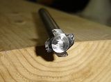
This is the cutting end of the threadmill. You can see the 4 flutes, the flat side of which is on the centerline. The hand-filed top and side relief show up well in this picture. When it dulled the edges seemed to roll over, like the cutting edge of a drill bit. To sharpen it I just filed a tiny bit on the flat cutting face to restore the corners. The OD of the cutter is something like 0.487 inches.
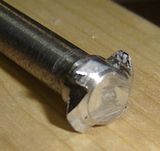
I don't know why the top of the triangle looks so truncated here, as it's not actually like that. Oh well, an optical delusion. I did file a small flat so that the thread root wasn't a sharp point. The face with the gray CPVC dust on it is the cutting edge, and the face I filed to resharpen.
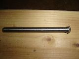
Overall view. The shank is turned down to fit a 21/64ths collet (I use TG100's). It's really long, which I needed to reach inside the part. I did mention that the milled threads do have a faceted look to them. This may be because I increased the control's error tolerance to 0.001, it may be due to chatter, or both. I didn't gage the threads - I didn't need to, they are simply for mechanically holding a cable strain relief in place and are not expected to seal against any pressure once the entire assembly is potted with the urethane. The cable strain reliefs are plastic, too, probably UHMW or something like that so minor errors in thread form and size aren't important.
I wouldn't expect my shop made threadmill to hold up in any metal, even aluminum. It worked fine in plastic, needing to be sharpened every 75 or so holes. I did try to make a multiflute threadmill to cut the whole thread in one helical revolution. This was a lot harder than it seems, as I needed to coordinate the thread lead and the depth of the 'V'. I wasn't successful in making a multiflute threadmill.
-
04-21-2011, 02:53 PM #7
Registered
- Join Date
- Sep 2006
- Posts
- 300
Fasto,
I like that. The video played great for me.
That is some good info on the thread mill. I have wondered about using a tool like a threading bar for a lathe and thread milling.
A lot of my tools are homemade. Brazed carbide & HSS.
Thanks for the info.
JAckalEverything is bio-degradable, if you run over it enough times with the lawnmower.
-
04-23-2011, 01:45 AM #8
Registered
- Join Date
- Jun 2008
- Posts
- 71
Looks like everything turned great. I do a bunch if thread milling on our Hurco and have been getting better at it. I have been doing some experimenting with a radial entry to see how that works, most of the milling i am doing is on stainless so I feel the radial entry is a little easier on the tool. Looks great!!
Bernie


 Reply With Quote


Similar Threads
-
i need parts made
By waldo2413 in forum Employment OpportunityReplies: 12Last Post: 02-06-2010, 07:56 PM -
Need parts made!
By Tim Wiltse in forum Hobby DiscussionReplies: 3Last Post: 08-05-2005, 06:41 AM -
Need some parts made and maybe more later.
By dmgdesigns in forum Employment OpportunityReplies: 3Last Post: 10-24-2004, 07:00 PM -
2 parts to be made ...
By WsW-WYATT in forum Employment OpportunityReplies: 7Last Post: 05-30-2004, 08:45 PM
