


Hello!
I have problem... Do anyone know suitable CAM-software for camshaft grinding?
I get cam shape in coordinates (half degree steps) software, what calculates
lift, angles and so on, but how I can transform it to G-code for CNC-grinding
machine?
Thread: CAM-software for Camshafts
Results 1 to 3 of 3
-
03-07-2009, 11:49 AM #1
 Registered
- Join Date
- Feb 2007
- Posts
- 171
CAM-software for Camshafts
-
03-08-2009, 03:53 PM #2
Member
- Join Date
- Jun 2007
- Posts
- 3735
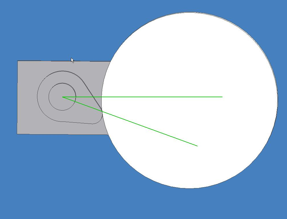
Toolpath.
The programmed 'toolpath' if we can call it that is a line grinding wheel radius from the desired surface of the cam. This is a similar problem to cutter radius compensation, but the applied principal is similar.
This link gives some insight into cutter radius compensation.
http://www.isd.mel.nist.gov/personne...8a.html#999268
This only works in the XY plane, so we need to calculate the compensation ourselves because the cam appears as a 4th axis being in degrees.
This requires a polar to rectangular conversion which can be done in line by a g-code interpreter.
You can solve trig and Pythagoras problems on the fly, where one of the main variables used will be the current wheel radius.
I haven't done any of this stuff before, so I call some experts who have already done it.
Not trivial, but some high school maths will solve the problem.
You need to treat grinding wheel like a very big cam follower.Super X3. 3600rpm. Sheridan 6"x24" Lathe + more. Three ways to fix things: The right way, the other way, and maybe your way, which is possibly a faster wrong way.
-
03-09-2009, 12:50 AM #3
Registered
- Join Date
- Feb 2009
- Posts
- 202
Camshaft CAM
Any cam software should be able to do this, the kicker is can you create a post that will out put nc code that your machine can run. For example, if I was going to grind a cam on an ANCA, I would rotate the A axis, and either feed the Z or X ( depending on wheel to part orientation ) as needed. I would use the system i have ( ESPRIT ) and post code. As i have created an ANCA post. I could also do this same process on a cnc lathe with C-X axis contouring, with a grinding wheel mounted on a live tool, or any mill/turn.
What machine do you have?

 Reply With Quote
Similar Threads
-
MIE Solutions - Free Quoting Software Trial Software available
By MIE Solutions in forum News AnnouncementsReplies: 0Last Post: 01-07-2009, 05:42 PM -
Milling Camshafts
By mikemill in forum I.C. EnginesReplies: 31Last Post: 01-04-2008, 04:21 PM -
First post in the software dept. Free cnc software?
By runinbymdnt in forum CNC (Mill / Lathe) Control Software (NC)Replies: 2Last Post: 02-07-2007, 04:49 AM -
Which CAD software???
By gus.montoya in forum Uncategorised CAM DiscussionReplies: 4Last Post: 06-24-2005, 12:57 PM
