


Hi guys, I'm a machine manufacturer in this field for years. I have dived in the forum for long time and worked backstage in R&D. some of you guys maybe are using machines with my design or solution.
This is my first thread and would like to share one of my development works of a small desktop CNC from designing, sketching, mould building, casting, machining etc. to last assembling and testing. Of course it's a formal product project, but I plan to just talk about the technology and building issues in this thread. Any comments and talk on this will be welcomed, I would like to share opinions with you guys in this thread or post message.
I plan to cover every key step to build the machine including machine structure, part assembling, control and electric system, enclosure etc. I will do every work I can handle by my own hands. So, let's enjoy it and hope everything go smooth...:violin:
Development aim:
total around 120KG, about 270lbs--weightness is the best guarantee of stifness and stable precision.
structure: casting irons of G3000 with heat treatment
three axis: linear guides with ball screws. considering use a commen class linear system with rolled type ball screws. I think it's enough for most applications.
axis drive: stepper system / DC servo system. not decided yet.
spindle: 1.5hp, 24000RPM electric spindle unit with VFD / or considering design a tiny mill spindle system with BLDC motor drive
electric system: transformer power supply for axis driver and develop a special VFD to support spindle.
control system: under considering now. should work with MACH software or other cnc software.
others: plan to add axis covers, enclosures, coolants etc. will update during the thread.

Results 1 to 20 of 3662
Hybrid View
-
07-30-2011, 10:14 AM #1
 Registered

- Join Date
- Jul 2011
- Posts
- 441
 Show how to build a CNC machine from the very beginning to the end
-
07-30-2011, 11:25 AM #2
Registered
- Join Date
- Jul 2011
- Posts
- 441
sorry for take some time to update pictures. I've done many designing works before on this machine with every part. the pictures show some process of the works under PTC. Once checked the models with software and soft assembling, we can do the real job then.
In my thoughts, I planed to make the machine have around 8"*5"*8" travel range, made of casting iron structure and linear guides, ball screws. with VFD controlled electric spindle unit and stepper drive system. Of course, as an option in future, mill spindle system and servo drive system can be also applied.
So it was designed to a mini precision cnc machine with strong structure. It can handle many material cuttings, from wood, plastic to aluminium, steel pieces. I think some guys may be interested in such small machines. at least it will be a good one for showing building process. I think this thread should be a long term one during my works. I hope you guys can give some comments. thanks.
-
07-30-2011, 03:31 PM #3
Registered
- Join Date
- Jul 2011
- Posts
- 441
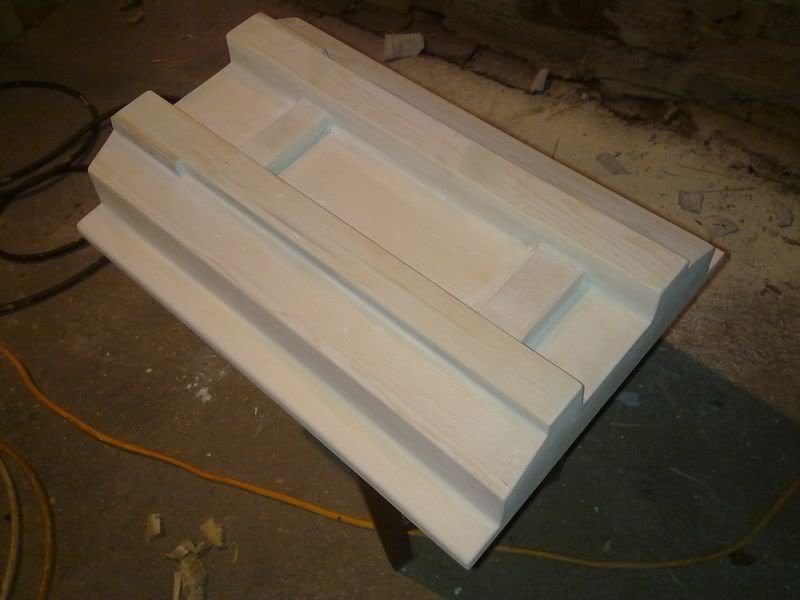
Firstly is the carpenter works to build the cast mould. The machine structure is not big, so I can work it by myself. I make the moulds using pinewood. It's a little soft and easy to treat. for long period casting process, it's not fitful because easy to transform after long time in high temperature and wet conditions. But for test works, it's no problem, especially after painting.
Now is the machine base part:
step1: make the frame of the base. stick the structure together and fasten it with nails.

bottom:

add more surface woods:

get the rough shape of the base now. It still has many longger wood and rough surfaces. but we have to wait until the glue dry and then take next steps.

The point of making the cast mold is to make the mold slightly bigger than the designed scale. normally, it will need about 1% bigger size because the cast iron will contract with cold after filled into sand molds. And, we can't forget to leave the spare size on machining surfaces. Normally, we need to leave about 0.15" spare size for machining.
-
07-30-2011, 04:14 PM #4
Registered
- Join Date
- Jul 2011
- Posts
- 0
These are good drawings, but I doubt this is a good time for honoring made in China machines, while our industry went down the tubes.
It was the US sending machines and production to China first, paying with massive job losses in electronic assembly and mechanical parts production.
Fortunately, I can see a gradual recovery in production, new designs and robotics classes in schools. The robotics FIRST competition leads the way in getting our kids exposed to robotics and parts manufacturing.
Growing up in Germany, I worked on designing steel manufacturing plants, also for Wuhan in China. Some years later our steel industry was dead. Than, I worked on fast pace electronic assembly machines, which is now dead as well with 90% production in China.
Now, I’m determined to bring production back to the US by teaching the next generation all about production, CNC machines and robotics.
I know, this is a technical forum, I do apologize for this post.
Regards,
Stefan
-
07-30-2011, 05:05 PM #5
Registered
- Join Date
- Jul 2011
- Posts
- 441
Thank you for your opinions and I think what you said is the reality of the whole manufacture field. And made in China is not a hornor for now. During my career, I often feel headache when facing the selection of many parts and suppliers. Everything gets to be the cost issue and consumable. It’s hard to find a good resource. If you want 10% better part, you need to pay more 100% cost. That’s the reality we are facing. So, as a China manufacturer want to product good machines, we have to balance many issues, and make hard choices. I prefer to work more by myself to make the best balance of every step, banlancing the quality and cost, and designing many parts by myself to avoid homogenization and make best value.
But, I think from an engineer’s opinion, technology has no difference between countries. I decided to post this thread from a hobbie angle. I tried to make the design as good as it can be, balancing the stifness, compact size, and even beautiful appearance etc.. I will show it step by step in this thread. I want to show different image of a China manufacturer------and a half hobbie.
Thanks again. Welcome for more comments.
Regards
-
09-26-2013, 07:28 AM #6
Junior Member


- Join Date
- Aug 2009
- Posts
- 44
good one, we also have the small machine. desktop style.
lele
Jinan jinshengxing machinery manufacture co.,ltd
Superstar brand
-
07-30-2011, 04:16 PM #7
Registered
- Join Date
- Jul 2011
- Posts
- 441
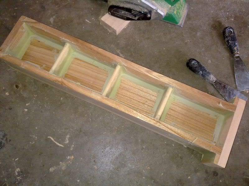
bottom sceen of the half finished base mold:

and one more word: When making a casting mold, make sure the side surfaces with a small angle, normally between 1 degree to 5 degree. larger angle will be better to make the cast process easier---easier to remove the mold from sand.
-
07-30-2011, 05:57 PM #8
Registered
- Join Date
- Jul 2011
- Posts
- 441
The column, work table etc. half finished. The works have been done several days before. I also have finished the last surface fixing and putty works to make the molds look more like wood model works. I will update the pictures tomorrow. Now I'm working on the small fixing and painting works.
the column:

stick the bottom to the column:

the Y axis slider:

the worktable:

the head: not sticked together yet.

the head: half finished.

okey. the rough building wood works finished here. Next, will be the boring and dirt putty, ground and painting works.
-
07-31-2011, 02:37 AM #9
Member
- Join Date
- Sep 2005
- Posts
- 1195
hi,
It is nice works. Do you cut that wooden mold using cnc router? I never seen people doing casting details like these here, just keep continue working. I follow your threads here as many other do too.
-
07-31-2011, 05:23 AM #10
Registered
- Join Date
- Jul 2011
- Posts
- 441
Thanks asuratman. I don't have a CNC wood router now. All works have been done by hand tools, a electric planer and a electric abrader. So the wood frame is divided to many small pieces to make seperately, and glue them together at last. It's a much more complex work than using a CNC router. I had to measure the scale many times during the work and fix the error. Originally Posted by asuratman

Casting process normally is far from our DIY works. We prefer to use materials like aluminium, which is easier to get and can get really nice work with machining. but aluminium is too soft for my machine. Another choice is steel material. But the welded structure has very big stress and cause transform to lose accuracy. So, casting iron is still the best choice for a strong and accurate structure.
-
07-31-2011, 02:43 AM #11
Gold Member
- Join Date
- Jun 2011
- Posts
- 695
I agree, this is an interesting build. Looking forward to the "pour".
-
07-31-2011, 05:26 AM #12
Registered
- Join Date
- Jul 2011
- Posts
- 441
Thanks for your attention, I will "pour" many details next. and welcome any comment. Originally Posted by FannBlade
-
08-01-2011, 02:33 PM #13
Registered
- Join Date
- Jul 2011
- Posts
- 0
No personal offense, but:
I fear you are going to early from drawing to a cast:
I mostly see straight wooden plates and too few taper angles as you mentioned.
Apparently, you tilted the plates, but the internal ribs look like straight plates.
It will be quite difficult to implement all the internal radii with filler.
In some areas the material is much thicker than in others, which will likely cause distortion in the cast. Consider beefing up the ribs to make them as thick as the walls.
The weight of the head doesn’t appear to be a match for the z-motor size. Have you done calculations or tests? Keep in mind, most data you get is the holding torque of a stepper, not the dynamic load. Do you have the efficiency data of Z lead screw?
I can’t detect any wiring of motors and limit switches in the drawing. If not implemented in the design, than you may need a hole here and there where there isn’t.
You mentioned coolant later to be added. So you’ll need skirts and covers for your linear bearings and ball screws. If not already implemented in the design, I fear, it will either not look pretty or skirts will leak against the iron cast.
There are no fasteners in your design, so I do assume you'll drill and tap holes later. I find this quite risky as you may oversee one or the other screw head can't be reached or needed to be counter sunk.
-
08-01-2011, 08:21 PM #14
Registered
- Join Date
- Jul 2011
- Posts
- 441
Hi Stewi. Thank you for further comments. Originally Posted by stewi
a. I do have place tappers for every side wall of the molds. and the tapers are not of the same angle. for some walls not too deep or apperant surface, using smaller angles, and for larger and machining surface, and especially inner ribs, use bigger angle. within the range of 1-5 degree. I think maybe the photos don't show the angles clearly. I will try to show the angles in photo after painting works.
b. I made the inner ribs seperatelly with tapper and glued them inside the frame. so It's easy work to make the ribs with angle. so no fllers will be needed.
c. Yes. The molds are not of the same thickness many places. It’s just the part need machining in future. After machining the slots and grooves etc, the thickness will have nearly same size so cause no dissortion. And, in formal manufacture, all castings need ageing treatment to eleminate inner stress to prevent it.
d. The head weight & Z motor torque issue is a important item. I agree with your opinions on motor torque issue and ballscrew efficiency issue. Both of them need to consider the dynamic spec. but not of the static ones. The motor size shown in the drawings are just use the same motor model with X, Y axis in PTC. The Z motor should be bigger than X,Y ones. And, there are also other way to solve this iss in industrial machines like balance weight method or N2 strut. I will test this during assembling and testing progress. All of the motor and ballscrew data are avaliable from supplier side and of course need to refer to the data sheet.
e. Yes I didn’t draw the wires and holes etc in the design and the fasteners also. I just have no much time to do so many detailed works. But they will be shown in CAD sketches that I also have finished now.
f. About the covers etc. You are correct that they must be added on the machine. I didn’t show them in the design because I have had many experience on similar machines and not a big problem for me. I promise you will see on finished machine.
And thank you for your detailed comments again. I think your comments are very helpful for building a machine. I’m sure you have many experiences in building machines. I’m very happy to discuss with you on further details.
Regards
-
07-31-2011, 07:17 AM #15
Registered
- Join Date
- Apr 2006
- Posts
- 169
interesting build
keep up the update pictures coming
nice work:wave:
-
07-31-2011, 09:06 AM #16
Registered
- Join Date
- Mar 2009
- Posts
- 39
Hallo Skyfire.This is fascinating.It looks like it will be a great machine.Nothing
commercial this size currently has linear guides.Can you tell us the weight of the
castings for head,column and base.Will you also cast the table yourself ?Please
keep posting.Thanks, Robert.
-
07-31-2011, 09:58 AM #17
Registered
- Join Date
- Jul 2011
- Posts
- 441
Hi, thanks for your comments. I think this size machine is not as commercial as bigger machines. But it's the machine I wanted to build by my hand for long time. I had some experience on bigger machines and I'm working on them now too. In this thread I want a table CNC can be put on desk and can do some small hard precision works that small routers can't do. The size is just a little bigger than SIEG X2. So maybe you want to build a higher end table CNC, it's fitful plan. Or I think maybe some place like labs, small metal workshop like jewelry etc will need such small but precision cnc machines. Originally Posted by shedbob
Sure, I can share the weight. Refering to PTC colculating, the weight are:
head:12KG / 26.5lbs
column:15KG / 33lbs
base: 18KG / 40lbs
I can't cast the parts by myself. It will need many other resources. I will send the molds to a casting factory for casting parts after I finish them. I think I may take some photos there to share with you guys.
-
07-31-2011, 09:43 AM #18
Registered
- Join Date
- Jul 2011
- Posts
- 441
Thanks, I'm planning to update some pictures today, but found my photo space is used up. I'm looking for another avaliable one now. Originally Posted by hesham morsy
-
10-17-2014, 03:37 AM #19
Member
- Join Date
- Jun 2014
- Posts
- 16
I'm curious about cnc machine because I studied language in college, now I'm doing the work for cnc machine sale.
-
07-31-2011, 10:18 AM #20
Registered
- Join Date
- Jul 2011
- Posts
- 441
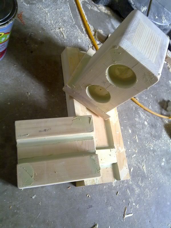
I get another usable photo gallery now. These several photos were taken in the putty works. This process is necessory for fixing small damages and round corners. Sharp corners are not good for casting process. It will cause sand fall down when filling in liquid iron. What's more, it will cause stress in the corner may cause frame transform or even broken.


Similar Threads
-
Show us your machine stands
By OHLEMANNR in forum Benchtop MachinesReplies: 7Last Post: 05-05-2013, 03:19 AM -
a machine design (pics) from beginning to end
By blurrycustoms in forum Vertical Mill, Lathe Project LogReplies: 42Last Post: 04-25-2013, 02:36 AM -
dry build or glue from the beginning?
By Ezra in forum Joes CNC Model 2006Replies: 2Last Post: 10-29-2010, 04:44 AM -
Newcastle: Beginning of build plan
By pippin88 in forum Australia, New Zealand Club HouseReplies: 7Last Post: 09-16-2010, 10:22 AM -
Beginning to build my Z-axis.
By zonk2 in forum DIY CNC Router Table MachinesReplies: 0Last Post: 12-23-2008, 06:17 AM
