


Okay, I'm new to the forums, and after being qouted $6800.00 from a local manufacturer to cut out plastic parts for a simple project, I've begun the search for an alternative. So now I'm here and reading and researching. I'm going to build my own machine (for hopefully half that cost) and cut them out myself.
After about a week of reading the forums here, and other places, I think I'm off to a good start.
So Here what I'm building:
- 49" x 97" Table (Cutting area)
- Vacuum system with individual zones and channels for hold down clamps
- steel frame construction with aluminum extrusion and plastic top
This is all i got so far. Still working on the Gantry design, motor placements, etc. Still trying to find a retailer for the Rack and Pinions before I can get the dimensions to draw those up.
Anyway, here's some pics.
Looking down from the top.
Looking from underneath. You can see the holes drilled for the Vacuum plumbing.
Close up shop of the back of the table. This is where the Gantry will rest when not in use. Also, you can see where the channels are for the hold downs.
Close up of the individual Tiles for the vacuum system and top. Will have a seal that sits in the outermost route.
Here is a close up of the bottom of the Tiles. You can see the channels for airflow, and also the routing for the inlay of the mesh screen for each hole. This is to hopefully keep the large debrees of dust/sawdust out. There will be a large filter as well, so the dust doesn't get into the pump.
This is all I have for now. Still working on it.
There are some questions I'm still needed to research.
- Will schedule 40 pvp pipe and valves work okay for the vacuum system?
- How wide of a rail will I need for the x-axis (the one the gantry slides on 97"), y-axis (the router carriage slides on 49"), and the z-axis?
Anyway, I'll try and update this as things come together. Money is an issue, so this won't be a project done over night. I'll need to save up some.
Thread: Started!
Results 1 to 20 of 161
Hybrid View
-
01-15-2012, 03:02 PM #1
 Registered
- Join Date
- Jan 2012
- Posts
- 394
Started!
-
01-15-2012, 03:19 PM #2
Community Moderator
- Join Date
- Mar 2003
- Posts
- 35538
Most use rack from Moore Gear and drive assemblies from CNCRouterParts.comStill trying to find a retailer for the Rack and Pinions before I can get the dimensions to draw those up.
Yes, they will. What kind of pump do you plan on using?Will schedule 40 pvp pipe and valves work okay for the vacuum system?
If you don't know what you're doing, it's easy to build a vacuum table that just won't work.
Do you mean linear bearing rails? What type do you plan on using?How wide of a rail will I need for the x-axis (the one the gantry slides on 97"), y-axis (the router carriage slides on 49"), and the z-axis?Gerry
UCCNC 2017 Screenset
http://www.thecncwoodworker.com/2017.html
Mach3 2010 Screenset
http://www.thecncwoodworker.com/2010.html
JointCAM - CNC Dovetails & Box Joints
http://www.g-forcecnc.com/jointcam.html
(Note: The opinions expressed in this post are my own and are not necessarily those of CNCzone and its management)
-
01-15-2012, 03:43 PM #3
Registered
- Join Date
- May 2005
- Posts
- 1662
a possible alternative ?
I've long wanted to try this but can't find 'tube board' locally.
http://www.cnczone.com/forums/cnc_wo...ble_build.html
Not sure how well the idea scales up.Anyone who says "It only goes together one way" has no imagination.
-
01-16-2012, 12:44 AM #4
Registered
- Join Date
- Jan 2012
- Posts
- 394
I was thinking these for the bearings:

However, I will get different bearings, the ones that are sealed and keep the grease inside. I worked on a CNC that had this style, and it was a nightmare cleaning it. The rails would get all dusty because of the grease.
And for the vacuum pump, I was thinking one of these:

Thanks on the PVC, I was racking my brain all night thinking they may not work. Lowe's says they only are rated for 150psi, and for some reason I think that the vacuum would cause more than that.
Anyway, what do you think of the design of the table, will it work?
What I'm hoping it will happen is it will perform like the one at work.
The one at work, you can throw a sheet of 1/2 MDF up there and the vacuum sucks through that and holds down your product to be cut. That way, You don't risk cutting/drilling into the table.
Will that pump be strong enough to do that? It's a 3000w, suppose to create a total of 180 cubic meters / hour.
-
01-16-2012, 12:47 AM #5
Registered
- Join Date
- Jan 2012
- Posts
- 394
When purchasing the NEMA 34 motors and the NEMA 23 (for the z-axis), what holding torque do I need?
-
01-16-2012, 03:56 AM #6
Registered
- Join Date
- Jul 2006
- Posts
- 1256
If you want to suck through a full 4X8 mdf spoil board you would need at least 25Hp vacuum.
Our machine at work uses the bearing blocks you have pictured.We do not use grease.
The grease nipples are fitted with tubing and have light oil at low pressure.No dust problems
As the mild pressure blows out the dust
LarryL GALILEO THE EPOXY SURFACE PLATE IS FLAT
-
01-16-2012, 04:50 AM #7
Community Moderator
- Join Date
- Mar 2003
- Posts
- 35538
Like Larry, I used to use a machine that had an automatic oiler on the blocks. Our current machine has an automatic greaser, pumping grease into the blocks regularly. When the grease is pumped, you get a small blob of grease on the outside of the blocks, but it eventually falls away. The grease is much neater than the oil, which could be a bit messy.
Almost forgot. 20mm rails are plenty strong enough.
I'm not sure how you're going to get the vacuum to all those "tiles". With a pump like that, you won't get much suction through small tubes. Those types of pumps generally use a single large tube into the table, with grooves in the table for the vacuum to draw from. They don't pull a very strong vacuum, but quite a bit of volume. However, the next step up would be about $8K-$10K for the pump.
Everyone always asks this, but nobody but you can answer it. You need to determine how fast you want to accelerate, and what rapid speeds you want, then, depending on the drive system, choose a motor that can supply the torque needed at your maximum rpm. Holding torque doesn't mean much, as it's the torque when the motor isn't spinning. You can buy two different motors with the same holdng torque, that will perform very differently for a given application.When purchasing the NEMA 34 motors and the NEMA 23 (for the z-axis), what holding torque do I need?Gerry
UCCNC 2017 Screenset
http://www.thecncwoodworker.com/2017.html
Mach3 2010 Screenset
http://www.thecncwoodworker.com/2010.html
JointCAM - CNC Dovetails & Box Joints
http://www.g-forcecnc.com/jointcam.html
(Note: The opinions expressed in this post are my own and are not necessarily those of CNCzone and its management)
-
02-02-2012, 11:56 PM #8
Registered
- Join Date
- Jan 2012
- Posts
- 394
Got more designed, and I think I'm ready to start buying parts/metal.
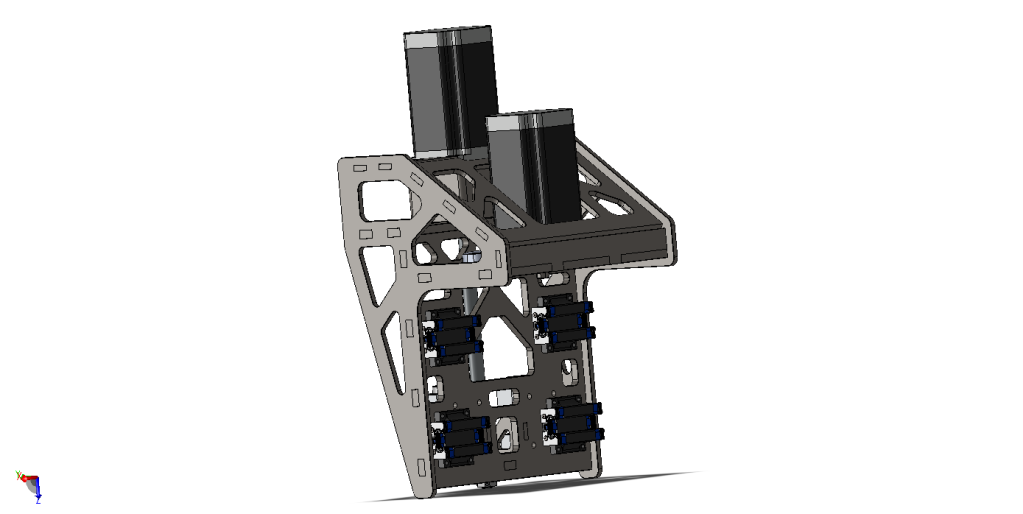
Here's some pics of the Gantry and Z-Axis. I think it's pretty stout.


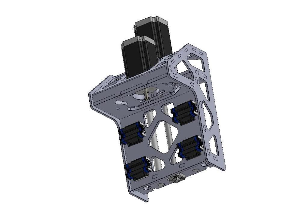
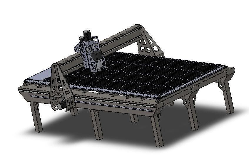
What do you guys think?
Overall travel of router is 54.3125" x 100" x 6.125"
I'm using 25mm rails and blocks for the Y-Axis, 20mm Rails and Blocks for the X-Axis, and 20mm Rod and 5/8" Ballscrew for the Z-Axis
The Gantry, with motors, should weight in at about 210lbs. I want to try and build this as solid as I can, because I plan on cutting Aluminum with it sometimes.
I still don't know hoe to calculate the motors I need. I want 2 motors for the Y-Axis, 1 for the X-Axis, and 1 for the Z-Axis, all NEMA 34's.
I will use the Gecko G540 Controller. What size Power Supply? Two 400watt be enough?
The Gantry weighs in at like 210lbs. I will use the gear parts from CNC Router Parts. This includes the weight of the router, motors (1600 oz.), and Z-Axis and will run along a rack and pinion of 100" in length, Motors on both sides. So, with that info, what motor size (x2) will I need for the Y-Axis.
The Z-axis will weigh in about 50 pounds (with motors and router) and will run along a rack and pinion of 66 inches. (That's with 1600 oz. Motors)
I've tried to read up and locate the calculations to do this, but I just can't figure it out. Now I know that 1600 oz. motors are probably NOT what I'm needing, I just added that as the weight just in case, so Gantry and Z-Axis MAY be lighter.
I don't know the speed IPM I need, or The Torque I need. Maybe others who have built similar dimensional tables can chime in here. I just want this table to cut efficiently and not chatter when I try and mill Aluminum.
This table will primarily be for cutting wood and plastic, but occasionally I'd want to cut up to 1/2" thick aluminum Plate.
I'll be using the 1.8° 200rev type Nema 34's
I'll be using the 2:1 NEMA 34's Gears from CNC Routerparts, using the 20pitch Rack and Pinions. (I'm just going to buy the gear plate, gear pully, pinion, and belt assembly from them).
The Ballscrew will probably be 10 lead, unless you guys think a 5 lead is better.
The other thing also, I was thinking of using the big 3-1/4 horsepower router from Porter-Cable. Is there a circuit or something I can get for that where the Cam Software can control the speed? The router says 5 speed settings, so I'm guessing it can be modified to be variable speed. If it can, then maybe I need to go with the Bosch Router.
As far as what I posted above on the Vaccuum system, I'm still searching that. That motor I posted is a 3-phase. Won't really work in a residential home. So I'm looking for another alternative.
Hopefully these problems can be resolved, because I'm ready to start buying up the parts, now that the Solidworks designs are done.
Thanks in advance Guys!
Jason
-
02-03-2012, 12:07 AM #9
Community Moderator
- Join Date
- Mar 2003
- Posts
- 35538
That's more a function of rigidity than motor choice. I think the linear bearing mounted so high on the Z axis may will make it a bit too flexible.I just want this table to cut efficiently and won't chatter when I try and mill Aluminum.
Imo, the G540 isn't powerful enough for Nema 34 motors. Better to use higher current motors and G201x's or G203V's.I will use the Gecko G540 Controller. What size Power Supply? Two 400watt be enough?
Also, I believe the G540 has a 7 amp fuse inside, so it can't draw more than 350 watts from a power supply (7 amps x 50 volts).
You can use a Super PID to control the 7518, but you need to remove the stock speed control. www.SuperPID.com - Super-PID Closed-loop Router Speed ControllerGerry
UCCNC 2017 Screenset
http://www.thecncwoodworker.com/2017.html
Mach3 2010 Screenset
http://www.thecncwoodworker.com/2010.html
JointCAM - CNC Dovetails & Box Joints
http://www.g-forcecnc.com/jointcam.html
(Note: The opinions expressed in this post are my own and are not necessarily those of CNCzone and its management)
-
02-03-2012, 12:51 AM #10
Registered
- Join Date
- Jan 2012
- Posts
- 394
hmm, okay
The linear bearings are mounted to a 3/8" thick steel plate and then the sides to give it support are 1/4" thick.
how else could I mount them? If I mount them lower, I'll lose Z-Travel. I plan to have a 6x6 solid maple (or other wood) by, say, 48" length on the table I plan on cutting flutes in using a round end mill bit. So, If I lower the Linear Bearings, It won't reach the table when I try and route oute 1/8" plastic.
I tried doing a Linear Rail and Bearing system using Rack And Pinion. Where the Railes fit on the side where the router is, then the support of the rails are full length, but, I'd have to use rack and pinion to make that work.
Anyway, thanks for the suggestions.
Would maybe upgrading to 1/2" steel for the Linear Bearing mount or taking out the holes stiffin it up enough?
-
02-03-2012, 12:52 AM #11
Registered
- Join Date
- Jan 2012
- Posts
- 394
OH, and also,
The Gecko drives, I would need 4 of those G203's, right? That just doubled the price, plus I'd have to spend more time to make the enclosure for them. Well, if it's what's needed, it's needed. I'll go stand on the street and ask for more change.
-
02-03-2012, 10:17 PM #12
Registered
- Join Date
- Mar 2011
- Posts
- 584
mount the linear rails on the back of the spindle holder bracket you have going there and attach the bearings on the Y carriage. Originally Posted by Falcon69

Not sure if I see how you can adjust the tension (gear mesh) on your Y axis.
And yep you'll need 4 steppers and drivers
-
02-03-2012, 11:52 PM #13
Registered
- Join Date
- Jan 2012
- Posts
- 394
Okay, i think I understand, I'll draw it up and post it to make sure. Will take me awhile to draw it up. SHould be there by tomorrow.
Any thoughts as to the size of the motors I need? (oz.) I want to start getting that stuff ordered.
-
02-05-2012, 01:07 AM #14
Registered
- Join Date
- Jan 2012
- Posts
- 394
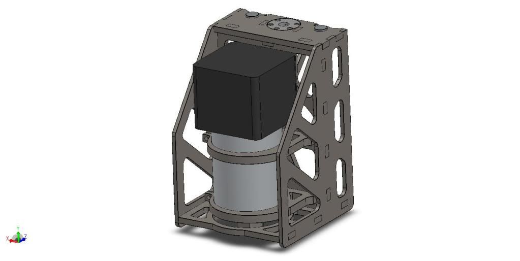
OKay, Here's the new drawings for the Z-Axis. Is this what you were talking about?
I can understand How it would be more stable when the router is up higher, but I don't really see any difference when it's dropped all the way down.


-
02-04-2012, 01:27 AM #15
Registered
- Join Date
- Jul 2006
- Posts
- 1256
you have been talking about 1600 oz steppers in past posts Way too big!Hopefully Gerry will chime in and explain.Taking a wild guess I would say 640 oz should be enough or the largest stepper to consider
LarryL GALILEO THE EPOXY SURFACE PLATE IS FLAT
-
02-04-2012, 03:10 AM #16
Registered
- Join Date
- Jan 2012
- Posts
- 394
Yup.
I know from reading and researching, 1600 oz is way too much. I just don't know how to do the calculation right. Now, is the 640oz. for the Y-Axis or X-axis, or Z-Axis? The Y-Axis will have to move the weight of the Gantry, Z-Axis, and the router, wherease the X-Axis just moves the Z-Axis and router, and the Z-Axis just the weight of the Router and those brackets.
So I'm guessing I'll need two motors of 'A'oz. for the Y-Axis, one motor of 'B' oz. for the X-Axis, and one motor of 'C' oz. for the Z-Axis.
Okay, enough for now, I'm done with daily chores, now to try and redesign the z-Axis. I think I understand what vtx1029 was talking about.
-
02-04-2012, 03:30 AM #17
Registered
- Join Date
- Mar 2011
- Posts
- 584
FYI most here refer to the longest axis as the X axis and your gantry axis as the Y axis. Not saying you have to call it that. Just kind of the norm
-
02-04-2012, 03:50 AM #18
Registered
- Join Date
- Jan 2012
- Posts
- 394
i thought so. LOL
For some reason someone in another post said differently, or so I understood it that way, so I thought I was wrong. LOL.
-
02-05-2012, 03:36 AM #19
Registered
- Join Date
- Jul 2006
- Posts
- 1256
Hay Fal
What material and thickness is the Z?L GALILEO THE EPOXY SURFACE PLATE IS FLAT
-
02-05-2012, 03:42 AM #20
Registered
- Join Date
- Jan 2012
- Posts
- 394
The pieces that the motor, Rail Blocks, rails bolted to, and Bearing blocks sit on are 3/8" steel. So the sides, and that top angle piece are 1/4" just to keep it rigid.


 Reply With Quote
Similar Threads
-
Getting started.
By Matt Ribble in forum Benchtop MachinesReplies: 3Last Post: 02-11-2012, 05:14 AM -
Just getting started
By tjones14 in forum Waterjet General TopicsReplies: 6Last Post: 02-25-2010, 10:36 PM -
It's started
By Max-DK in forum CNC Wood Router Project LogReplies: 2Last Post: 02-04-2008, 03:45 AM -
getting started in CNC. need all the help i can get :)
By slow_rider in forum Benchtop MachinesReplies: 13Last Post: 10-22-2006, 05:42 PM -
Just getting started
By BobWarfield in forum Rhino 3DReplies: 1Last Post: 03-28-2006, 04:19 AM
