


Hi all,
another member of a dutch scalemodeling Forum gave me this link, and now i got here, i might as well share my designs with you.
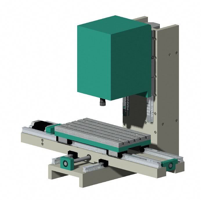
last summer i got a PC and 3 stepper motors, to fit to a 3-axis milling machine, but i have one problem.. i'm a professional tool maker, and i want the quality that i have at work ( Bridgeport VMC800 ) so i designed a 3 ( 4th axis will be mounted on the table ) machine.
Workspace will be 280 x 140 x 165 millimeters ( yup i'm from holland.. i dont work with inches.. too many numbers behind the comma )
Maybe showing my design will rule out any design flaws i overlooked.. though building is already in progress..
i also managed to get hold of a steel cabinet 100 Cm's high, and 70 x 50 Cm's top surface.. the milling machine wil be bolted on top, and i'm planning om making a casing/shield with plexiglass windows and a TFT screen in the door(s)
Spec's sofar:
Motor 600W router, 7000-30000 RPM's 6 mm collet ( smaller collets wil be made in the near future)
stepper motors from Vexta, 2.5 A, 2.2 Ohms Nema 23
Rexroth Ballrail guides and Ball spindles.
Machine frame is made out of construction steel 15mm thick in most places except the X-axis guide bed which is 30x40 mm's 596 mm's long.
Fourth axis will be built in a Unit which can be bolted on the table ( design hasn't been made yet, i'm still searching for small 4 jaw independent Chucks.
Progress sofar: machineframe is finished, al parts are ground flat only the Z-axis milling head is still to be made, if that's finished, the rails wil be bolted on.
Results 1 to 20 of 441
Hybrid View
-
01-10-2007, 11:31 PM #1
 Member
- Join Date
- Jan 2007
- Posts
- 352
My First CNC, own design, buidling in progress
-
01-11-2007, 12:28 AM #2
Registered
- Join Date
- Mar 2003
- Posts
- 2139
What is it you will cut with it?
What drivers will you use?
EricI wish it wouldn't crash.
-
01-11-2007, 04:57 PM #3
Member
- Join Date
- Jan 2007
- Posts
- 352
I bought drivers from www.stappenmotor.nl located in Holland.. 49.50 Euro's per axis, which basically means 200,- for 4 axes.
the machine will be tough enough to machine steel, Bronze, PU, Resin, Foam, Brass, silver, and maybe even hardened steel.
i'm building it to machine things like this:
scale is 1:24, but i want to make more parts for scale modeling purposes.
the PC is already "hooked-up" with the drivers, and some motors for testing.
Currently the motors operate on 12V, but the drivers are able to use a current up to 30 Volts, so i'm also searching for a 30 V DC Powersupply.
Bit of luck today.. i now actually have the steel cabinet, so i can start to take measurements to build the casing.
-
01-13-2007, 12:52 AM #4
Registered
- Join Date
- Mar 2003
- Posts
- 2139
Cool.
The spindle rpm might be a little high for machining steel...but you know that since you are a tool maker.
Let's see picturs of the build!
EricI wish it wouldn't crash.
-
01-13-2007, 09:44 AM #5
Member
- Join Date
- Jan 2007
- Posts
- 352
with a spindle speed of 7000 Rpm you'll get a 130m/min cuttingspeed with a 6 mm end mill, with this speed i'd be able to even machine Tool steel, and hardened steel with a solid carbide tool.
30000 Rpm will provide a cuttingspeed of about 50 m/min to a 0.5mm end mill, will do.. a 2 mm end mill will run 188 m/min wich is perfect for machining steel. ( data based on Solid carbide tools) .
Ok.. enough Tech-talk for now... Here are some pictures..
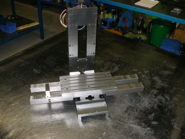
Machine frame sofar, the mill head is still to be made, the guides must also be bolted on
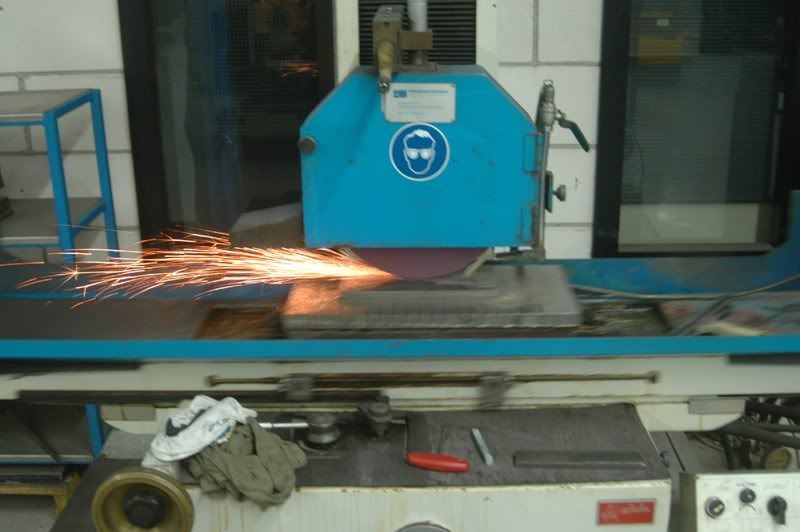
Yahooo !! Sparks!!.. flatgrinding the Z-motorsupport and the Z-spindlebearing support
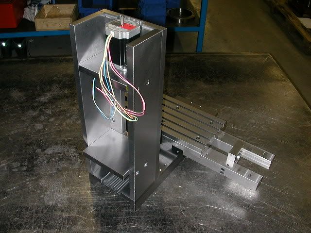
suport plates mounted in place, note: the Bearing support, in the bottom of the collumn is machined to size by now..
Z-motor also mounted, to see if all would fit.. yup it fits like a glove..\
Enjoy the pictures!
-
01-16-2007, 10:41 PM #6
Registered
- Join Date
- Mar 2003
- Posts
- 2139
It's an awesome machine. Originally Posted by arie kabaalstra

Is the above m/min or mm/min? If it's m/min it's going to be tough getting that axis moving that fast on the drives you are using. I would say your speed will max out at around 150-200 mm/min being that the drives max voltage is 30 volts, using any reasonable pitch ball screw, and coupling them to the lead screw directly.
EricI wish it wouldn't crash.
-
01-16-2007, 11:51 PM #7
Member
- Join Date
- Jan 2007
- Posts
- 352
the speeds in the Qoute are the rotation ( cutting ) speeds, not the table feeds
i had my steppers run @ 22Khz, which gives me about 800 revs on the steppers, with a 2 mm pitch on my leadscrews that'll be around 1.6 M/min or 1600 MM/min table feed on 12Vdc.. needless to say these values will increase with higher voltages..
also, i can always fit "heavier motors".. as long as they're Nema 23 Bipolar ones
-
01-13-2007, 11:02 AM #8
Registered
- Join Date
- May 2005
- Posts
- 674
Lookin' good!
-
01-13-2007, 11:19 AM #9
Gold Member
- Join Date
- Nov 2004
- Posts
- 131
Wow, looks great.
Great pictures too.____________________________________
Jeroen
-
01-13-2007, 11:42 AM #10
Registered
- Join Date
- Jan 2005
- Posts
- 224
Congratulations! Finally a precision small DIY mill with full support of the X axis.
Hope it works as good as it looks like it will.
It would be interesting to me to know what one would charge to build a machine like that.
(i.e. make a living at it - pricewise)
Good luck,
Pres
-
01-13-2007, 12:21 PM #11
Member
- Join Date
- Jan 2007
- Posts
- 352
Originally Posted by Pres
wat it will cost?.. if i'd have to make a living from building these, i'd be bankrupt in a few weeks... considering i constructed the entire machine, and i'm also building it, and it has taken me a full week to design the thing, and a lot of hours grinding, milling, drilling and so on..precision comes at a price..
the Full X-axis support is needed to get the accuracy i want.. the 596 mm long supoprt beams are ground flat within 0.01 ( and that's before the X-axis Guides have been mounted )
Yesterday i did another very important Job for this machine, i made 36 of these:
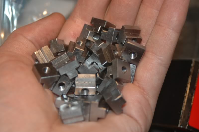
T-Nuts 12X12X9 mm with M5 Thread to clamp future workpieces
-
01-13-2007, 12:54 PM #12
Registered
- Join Date
- Jun 2006
- Posts
- 47
ow my god! now that's nice! looks even better then a X3!
goed bezig gast! Blijven posten zou ik zeggen
-
01-13-2007, 01:36 PM #13
Member
- Join Date
- Jan 2007
- Posts
- 352
Basically, all i did was take a good look at what i have at work, a Bridgeport VMC 800, and a VMC 610XP, the 800 has the long travel the 610 is equipped with ball rail guides..mix these two together, and what you get is what i designed.. ( japanese engineering, see what's around, and mixing the best features )
X3?.. if the X3 is the "Sieg X3 mill" then i'd say.. "That's not a CNC mill, that's a conventional machine with a retrofit, still a drill press with cross slides, and the x-axisguide is just too short.. " But it's an affordable machine, which mine isn't by definition.. if i'd have to build them commercially, boy would it cost'ya
Since i'm a toolmaker by profession, construction steel is available at low cost, so are the machines.
The guides will be ordered shortly, we're building other machines for out R&D dept. at the moment, and those machines also have a couple of ballscrews , so mine will be ordered at the same time to get a discount..
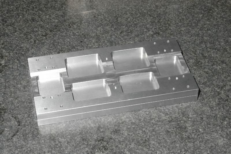
This is the table, i milled some pockets in the tableframe, to reduce weight, since this part wil run the highest feeds ( 2500mm/min )
i'm considering to sell plans of this machine, though i'm not sure the design is "buildable" for others, since a lot of grinding is needed to straighten parts after milling..
-
01-16-2008, 02:51 PM #14
Registered
- Join Date
- Jan 2008
- Posts
- 1
 Motor and linear motion specs
I'm new to this type of project and I'm blown away by the quality of machine you've created.
Would you mind posting Model No's etc for the Motors, ballscrews and linear guides. There is such a range of screws, nut etc, so that I could get an idea about which are suitable for a project like this?
-
02-14-2007, 10:14 PM #15
Registered
- Join Date
- May 2005
- Posts
- 674
Come on, man. That's a horrible comparison. An X3 is an absolute piece of junk compared this machine. (nuts) Originally Posted by Brunow
-
02-14-2007, 10:34 PM #16
Member
- Join Date
- Jan 2007
- Posts
- 352
isn't that what i said earlier in this topic?..
this evening i dusted down my trusty ol' Proxxon ( even less than an X3.. it's manually operated, but it's an accurate piece of equipment )
X3?.. if the X3 is the "Sieg X3 mill" then i'd say.. "That's not a CNC mill, that's a conventional machine with a retrofit, still a drill press with cross slides, and the x-axisguide is just too short.. " But it's an affordable machine, which mine isn't by definition.. if i'd have to build them commercially, boy would it cost'ya
what did i do with my little old hobby mill?.. well.. to put it short.. what's a probe, if it doesn't "sense" anything?.. correct.. a nice piece of "nutt'n" so... i installed the "nerve system..
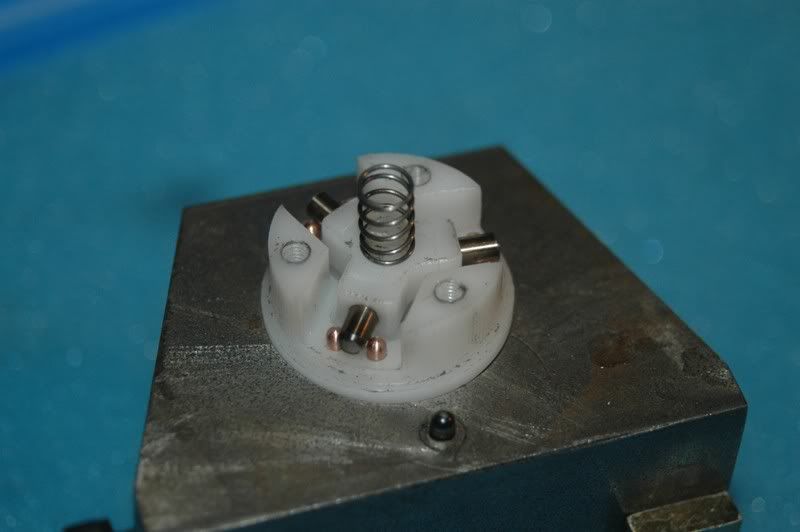
these are the contact pins ( made of Berryllium Copper which is much harder than normal copper )
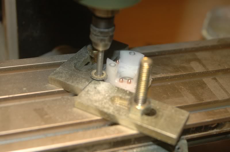
then i fired up my Proxxon, to make some room for the electric wires
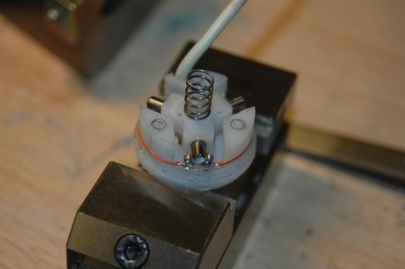
Then.. a very precise job.. soldering the wires, and trying not to melt the delrin body.. the lead to the CNC control used to be a microphone cable ( coaxial ), nice and supple...
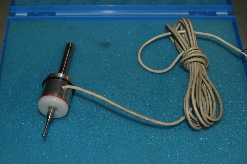
Leading all to: The End result.. a nice little Probe, i've already tested it, Hooked up my Fluke, and as soon as anything touches the probe, it switches
( by the way.. Zumba.. Go easy on Brunow, i know him from the Dutch CNCzone ( www.cnczone.nl ) were i also have a topic on this little machine..:withstupi )
-
02-14-2007, 10:45 PM #17
Member
- Join Date
- Jan 2007
- Posts
- 352
@ Zumba:
Yup.. i Surface ground every part.. Why?.. can't help it.. i'm a professional tool maker..
Cold rolled steel is generally considered "accurate" in dimension.. if you don't have the means of measuring ( Granite table, surface grinder ) you'll never find out if it's bent, warped, or otherwise distorted.. distortion of standard cold rolled steel is generally within 0.1 mm, that doesn't sound like an awful lot, but to me it is... ( made a slide assembly with only 0.005 mm clearing last year )
so.. i have a basic rule : First, deburr, then check for distortion, then grind, to make all sides perfectly parallel ( within 0.005 mm ) then mill, drill wire erode or whatever means of machining i need to do..
i don't take accuracy of materials or machines for granted.. that's the main difference between a "normal steel worker" which is an expert already, and a toolmaker, toolmakers just take one step beyond..
the bottom of the pockets in the mill table, is ground, that's why it is so shiny, but the sides are milled..( the table is in 2 parts )
milling is done whith Carbide endmills with a TiAln Coating, cuttingspeed 300m/min, and 800-1200 mm feed but i don't machine everything down to size in one pass.. i leave 0.2 mm material on, and then finish the parts, this way, i know all dimensions are within ± 0.05 mm which is " my basic tolerance "
-
01-13-2007, 03:33 PM #18
Member
- Join Date
- Jun 2005
- Posts
- 3502
Arie,
I'm impressed so far, it's nice to see that others have an eye for detail!
I like your initial design, as its all steel!
Eric
-
07-26-2007, 11:46 AM #19
Member
- Join Date
- Apr 2007
- Posts
- 273
looks good
looks great but it looks like you are going to lose some travel on your x axis with the way you have your motor mounts set up.
-
01-13-2007, 04:04 PM #20
Registered
- Join Date
- Jan 2006
- Posts
- 357
That is a fantastic looking machine!!, I will be watching this thead

 Reply With Quote
Similar Threads
-
more progress..
By adam_m in forum DIY CNC Router Table MachinesReplies: 0Last Post: 11-26-2013, 03:56 AM -
Design In Progress
By JoeDawg in forum Uncategorised MetalWorking MachinesReplies: 1Last Post: 10-07-2008, 07:48 PM -
My First Router Design & Progress
By watsonstudios in forum CNC Wood Router Project LogReplies: 40Last Post: 07-22-2007, 09:19 AM -
Looking into buidling an Auto-start RPC
By Wendell in forum Phase ConvertersReplies: 2Last Post: 10-12-2006, 03:03 AM -
Alibre design in progress
By xyzcnc in forum Uncategorised CAD DiscussionReplies: 10Last Post: 06-07-2005, 06:49 AM
