


Hi everybody,
New here so please tell me if I do something wrong, like posting this in the wrong section or something.
Now, I've built myself a small milling machine for light machining like aluminum, plastics etc. I've had it for a couple of years and at first I used a Bosch router but quite quickly changed to a homemade ER16 collet spindle. This spindle has proven to work for what I do but I wanted the benefits of quicker and repetable toolchanges and the possibillity to go full ATC (but I probably won't on this machine).
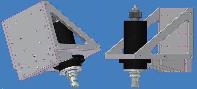
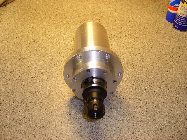
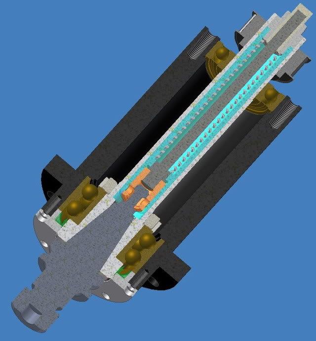
After quite a while researching other spindle projects here, and elsewhere I started to design around a BT30 holder with a 45 degree pullstud. The final design ended up looking like this:
The two lower bearings are angular contact 7207BEGAP and the top bearing is a standard 6206. Allthough I'd love to have "special purpose spindle bearings" I hope that these will be good enough. They are universally matched and ground for a light preload. My aim is to be able to run somewhere between 6000-8000 rpm but we'll see.
There's a coilspring in the drawing but that is of course belleville washers in the real spindle. 114pcs of them provides around 3000N when the taper of the tool holder makes contact with the spindle taper.
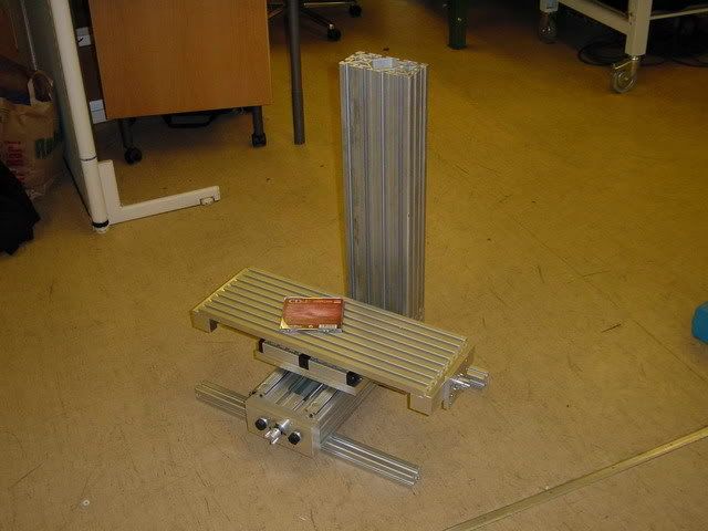
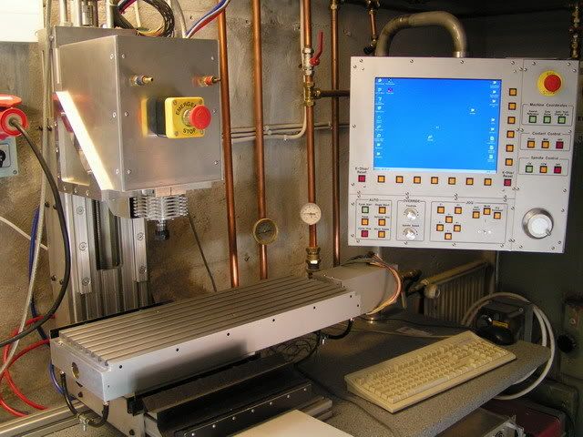
And here's the machine it will hopefully end up on when finished:
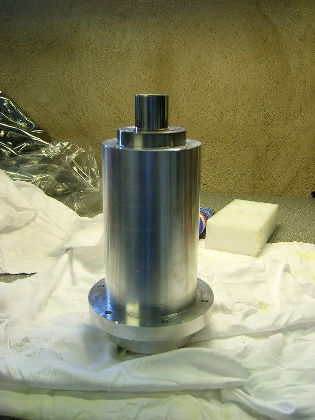
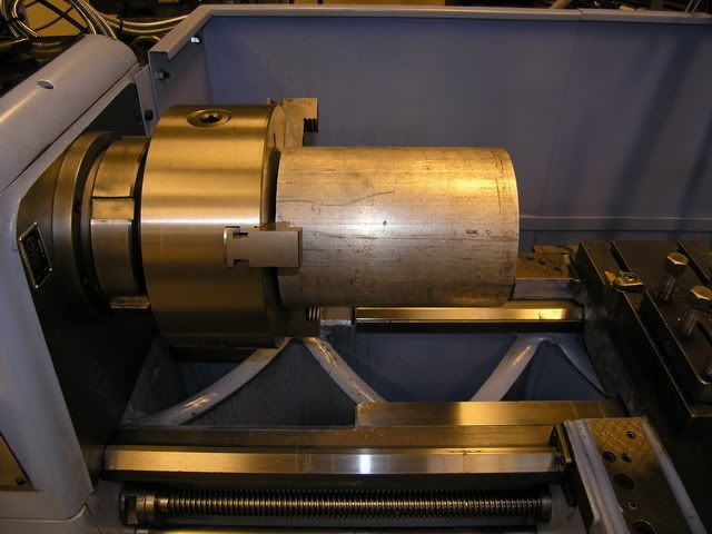
I started by making the housing for the spindle. At first I intended to make it out of steel or even stainless but changed my mind and made it out of aluminum. If it turns out to be bad choise I'll either make new one or have one made (I don't want to do it again, see below...) Anyway, here's a couple of photos of the process:
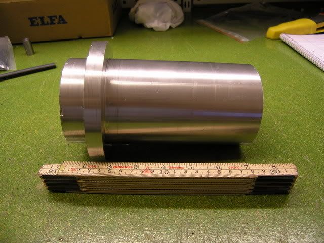
160mm dia aluminum round bar ready for machining:
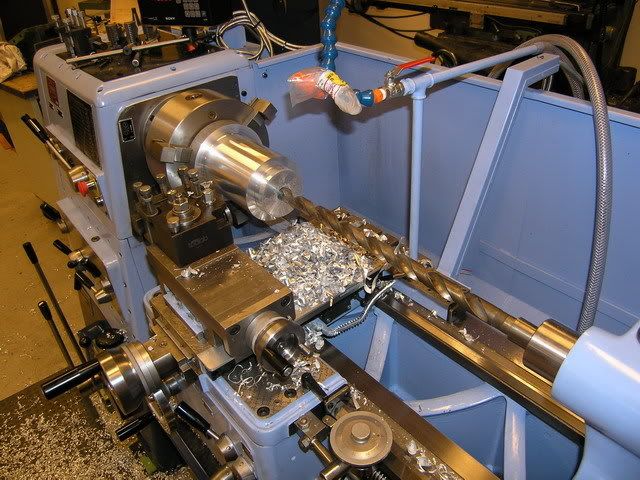
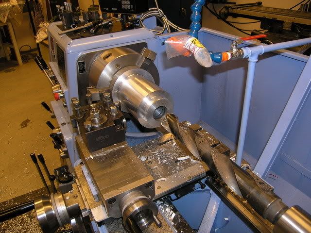
I turned down the outer diameter of the lower part and the flange and then started to drill out the ID:
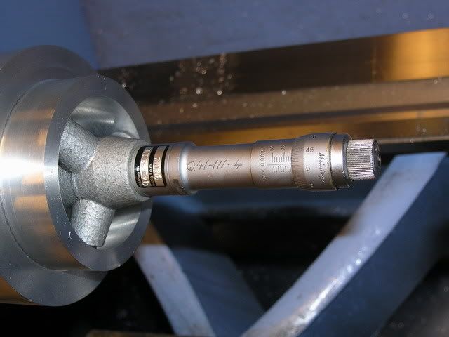
When the bulk of the material was drilled out I machined the seat for the lower bearings, here I'm using a three-point micrometer to measure the diameter - 71.985mm for a 72mm bearing:
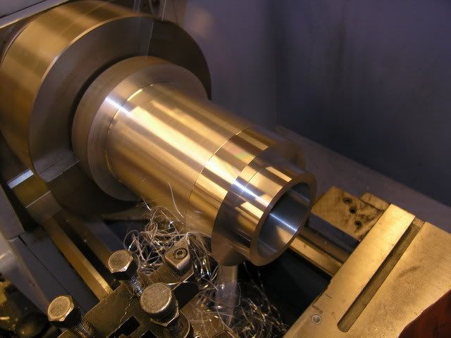
With the lower bearing seat done I brought the OD to its final dimensions 90mm and 125mm for the flange:
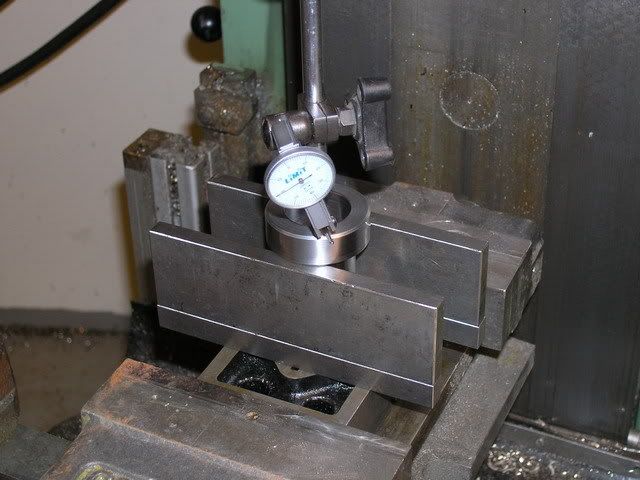
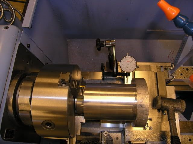
I then made a "plug" that fits in the bore for the lower bearings so that I shouldn't deform the bore when clamping it in the chuck. Then I indicated it as true as I could. I got it to within 0.01mm:
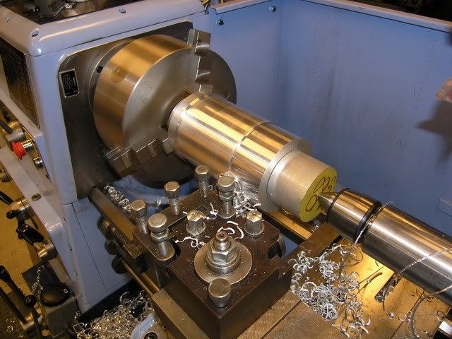
Then I machined off the excess material and made the bore for the top bearing. The live center wasn't big enough to fit in the 62mm bore for the top bearing so I made another plug to use as support while maching the rest of the OD down from 125mm to 90mm:
When I was ready to finish the top end I found that the fit between the top "plug" and bore was a little too tight so I had to remove the whole setup from the lathe in order to remove the plug. When resetting it up I didn't tighten the the chuck enough (I was affraid to deform the lower bearing bore)and the whole housing came loose while finishing off the top end....ouch... It seems to be OK though, time will tell. (You can see the dents from the jaws in the photo)
My intention was to have the housing anodized but with all the uggly marks in it I'll leave it as it is.
That's it for my first post here. More later.
/H.O
Thread: BT30 Spindle project
Results 1 to 20 of 174
Hybrid View
-
07-28-2007, 07:17 PM #1
 Registered
- Join Date
- Jul 2007
- Posts
- 887
BT30 Spindle project
-
07-28-2007, 07:53 PM #2
Registered
- Join Date
- Jul 2007
- Posts
- 887
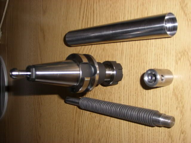
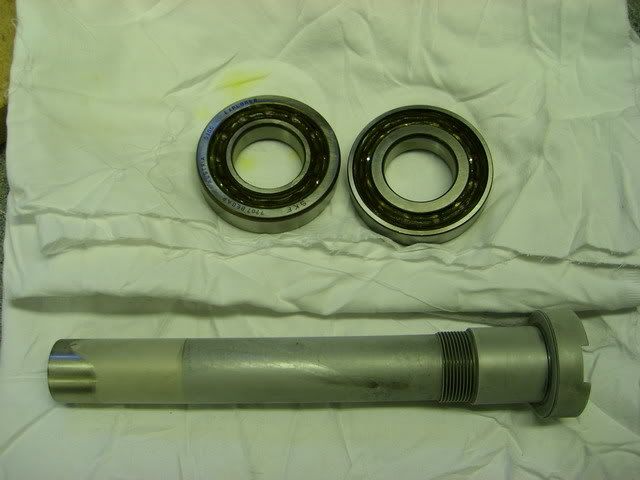
When the housing was done I started to make the internal parts of the spindle. The gripper, drawbar and the tube that will house the drawbar assembly. I don't have any photos of the actuall machining but here's a few of the finnished parts.
Drawbar with springs, the gripper and tube and a BT30 holder:
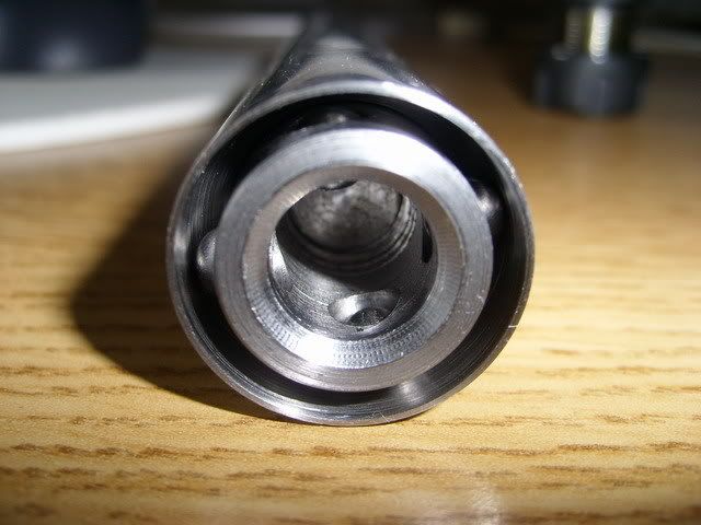
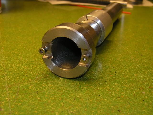
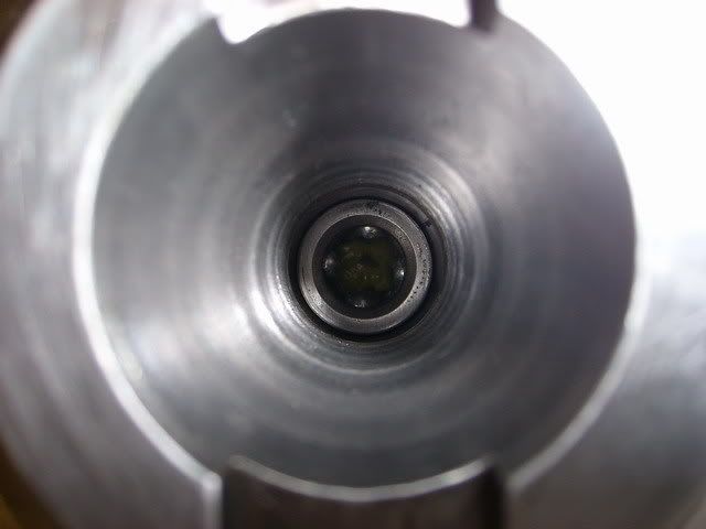
Here's the tube and gripper viewed from the end that grips the toolholder. The holes in the gripper is a reamed to 6mm for the balls but not quite all the way thru to prevent the balls from falling out.
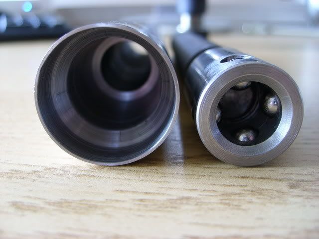
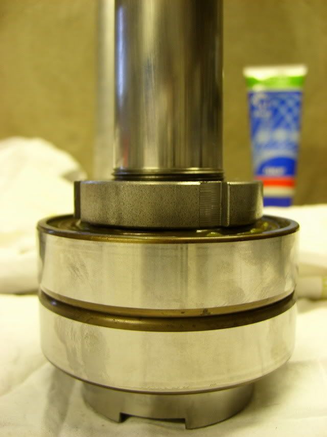
And here's another one when it's assembled. When the springs pull the drawbar up, the chamfer in the tube will force the balls inwards gripping around the pullstud of the holder. A pnuematic cylinder will push the drawbar down to release the tool - I believe this is how most toolchanger works. This assembly will then be mounted inside the spindle from the top as can be seen in the 3D model in the first post.
More later, thanks for looking!
/H.O
-
07-28-2007, 07:57 PM #3
Registered
- Join Date
- Jun 2005
- Posts
- 1015
thats a pretty serious endeavor. what spindle speed are you shooting for? also the whole setup looks good, can't wait to see the final product.
-
07-28-2007, 08:04 PM #4
Gold Member
- Join Date
- Jun 2003
- Posts
- 2103
great looking work
Keep the updates and photos coming! This looks like a good project.
Any chance of getting to post the drawings.....hint, hint, beg beg!!!
MikeNo greater love can a man have than this, that he give his life for a friend.
-
07-28-2007, 08:14 PM #5
Registered
- Join Date
- Jul 2007
- Posts
- 887
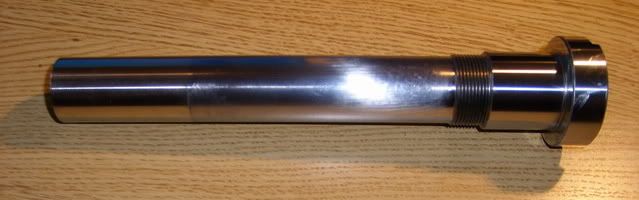
Next task to tackle was making the actual spindleshaft. It's made of steel (2511) and the lower end will be hardened and ground. Here's a photo of how it looked after the first operation:
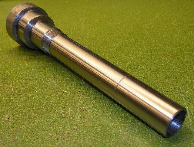
The threads are M32 X 1,5 and will be used to press the inner rings of the two lower bearing together. The outer rings will be pressed together by the lower flange. What's left to do here is an internal thread at the top that will be used to hold the drawbar assembly in place as well as preloading the spring washers. And to machine it to length and turn the taper for the toolholder.
Turning the taper wasn't as easy as I thought it would be, (never done it before) it took two testpieces and a lot of fine adjusting the cross-slide to get it good enough.
Here's a photo of the setup I did when milling the slots for the drivdogs. I made a "collet" to hold the shaft while maching the taper and used it in this setup as well to clamp the shaft between two vee-blocks.
And here's the finished spindleshaft. You can see the "collet" just above the threaded section.
The spindle shaft and the drawbar assembly have now been sent out for hardening and grinding. Hopefully I'll have it back in a week or two.
Thanks!
/H.O
-
07-29-2007, 09:39 AM #6
Registered
- Join Date
- Jul 2007
- Posts
- 887
Hi,
Thanks guys!
I'm hoping to get 6000-8000 rpm. The bearings are rated for 12000 but should be derated by 20% when mounted in pairs so that's 9600rpm but then there's the front seal which have a max surface speed of 18m/sec. The diameter of the part that makes contact with the seal is 50mm and that makes the top speed around 7000.
I turned the diameter to exactly 50mm but then the grindning will make it a little smaller so the contact pressure from the seal will be a little less than by default, hopefully that will make it last longer but still provide enough seeling for this application.
At 8000rpm we are also approaching speeds where balanced tooling may be required (or so I've read) and that's something I don't think I'm gonna afford. Hopefully I'm not going to need to balance the spindle itself.
I'll see what I can do about those drawings. Right now I don't dare to publish them as I need to clean them up a bit. Besides, I wan't to see if the damn thing works first.
/H.O
-
07-29-2007, 10:04 AM #7
Gold Member
- Join Date
- Aug 2006
- Posts
- 1602
Wow - excellent work, thanks for sharing it

Do you have any build pics of that mill itself?
-
03-01-2009, 07:54 PM #8
Registered
- Join Date
- Apr 2007
- Posts
- 1
Hi,
This is my first time writing something on the forum and saw what you put information regarding tool change it is briliant.
Thanks
Ashok Kumar
-
04-10-2009, 12:59 AM #9
Registered

- Join Date
- Jan 2007
- Posts
- 219
Well its been a few months since your last update. Has there been any progress? How do you like the knee mill?
-Adamwww.adambrunette.com - Converting My Harbor Freight X2 And My Jet Jvm-830 Knee Mill, As well as many other projects.
-
04-10-2009, 10:35 AM #10
Registered
- Join Date
- Jul 2007
- Posts
- 887
Hi,
No, no progress on the spindle project :-(
The current status is that the spindle itself is stright and runs true. When fitting a tool and pulling it up in the taper with a threaded instead of the gripper type drawbar the runout is very reasonable, below 0.01mm.
When using the gripper type drawbar something goes wrong and the runout is totally unacceptable. My theory, as I've written before is that the drawbar pushes radially on the top of the tool making it "tilt" in the taper. So close, yet so far away - frustrating. Someday I'll open up the drawbar tube even more and see if that helps.
Progress is being made on the knee-mill although it a slow project. I'm getting there though, I'll make a thread here in a while.
/Henrik.
-
07-29-2007, 02:35 PM #11
Registered
- Join Date
- May 2003
- Posts
- 40
Fantastic work so far, very nice and accurate machining! I am very interested in the BT30 format so I will definitely be following this thread. Keep us posted on your progress.
Carvejunky
-
07-29-2007, 03:44 PM #12
Registered
- Join Date
- Jul 2007
- Posts
- 887
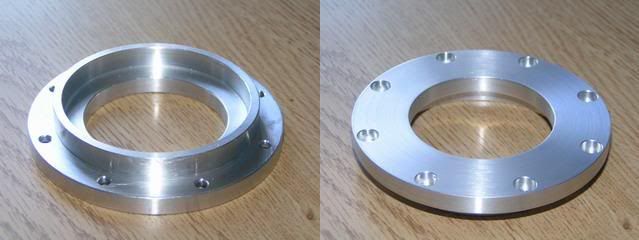
After sending the parts out for hardening and grinding I made the flange that will keep the lower bearings outer races togehter as well as house the seal. It turned out quite nice:
I also picked up a pneumatic cylinder for the drawbar. It's a 100mm bore, double acting and will provide the required force to compress the spring washers. It has a stroke of 50mm which is way to long so I'll probably end up shortening it quite a bit.
If my calcualtions are right the clamping force will be around 3000N and it will take around 4500N to press the drawbar down far enough for the tool to come out.
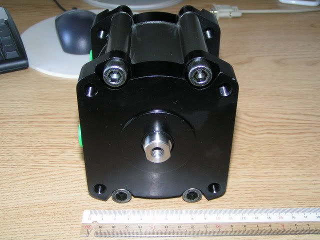
And this is how it hopefully will end when it's done:
I haven't figured out how to mount the motor yet. It may very well be that I have to change to a smaller motor in order to able to fit it, but we'll see when the time comes.
About the machine itself. I don't have that many pictures of the actual building process but I'll attach a couple here. It's built around a Bosch alu-extrusion 190X80mm and uses ISEL ballscrews and linear ways. The first photo shows the machine with X- & Y-axis ready:
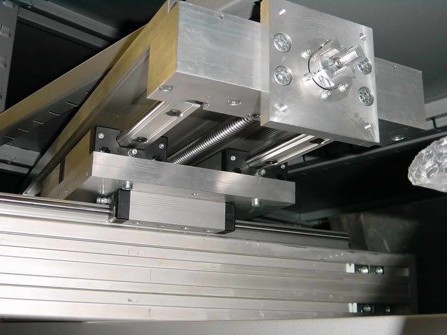
Next one i a closup of the bottom side showing the ballscrew, linear ways, bearing blocks, motor mounts, and shaft coupler. Each ballscrew has two 7200B angular contact bearings at the driven end and a single deep groove ballbearing at the other end.
Here's one showing it with the ER16 spindle that is currently on the machine. The motor is 1100W three-phase controlled by a VFD from Mach3.

The stepper motors are ~3.5Nm driven by Geckodrive G210's
There's also a video of it on Youtube running a "demo part".
Sorry for drifting off topic here. But it was by request ;-)
Tomorrow I will call the shop doing the grinding and see how it goes.
/H.O
-
08-07-2007, 06:42 AM #13
Registered

- Join Date
- Jul 2005
- Posts
- 340
hello, fine work with the spindle! didn`t you think about seal upper bearing ?
any news ? more pics please :-) and a video at the end ;-)
-
08-07-2007, 04:21 PM #14
Registered
- Join Date
- Jul 2007
- Posts
- 887
Hi,
The upper bearing is a sealed bearing. There won't be much chips or coolant flying around in that region so an extra seal up there seemed like overkill.
I actually have a small update, not a very good one but never the less....
Here's the deal: The shop that does the hardening and grindig asked me to leave 0.4mm on the surfaces that I wanted to get hardened and ground - and so I did. Since the upper part of the shaft wasn't going to be either hardened OR ground I turned that part to final dimensions. Do I regret that or what?? The heat from the hardening made the upper part of the shaft oval which means that turning or grinding it back to round will make it WAY to small for the upper bearing to fit properly.
Not to whorry though, yesterday I sent the shaft out to get the upper part electroplated so there's enough material all the way around. Then the whole shaft will be grinded so it's round and the upper part for the bearing fit.
More time, more money, one lesson learned...
Will be a couple of weeks, I guess, before any more progress can be made on this project but I'll post as soon as I get the shaft back.
Thanks!
/H.O
-
08-28-2007, 10:09 PM #15
Registered
- Join Date
- May 2006
- Posts
- 573
Any chances you wanna share the drawings with us? Ive been wanting to make a atc spindle for a long time. Actually bought a lathe and retrofittet it for the same reason.
Edit: I read this thread a 100 times, but somehow missed that im not the first to ask:-) Anyway, the request still stands. But ill wait and see how it turns out before i even consider to start
-
08-29-2007, 06:44 PM #16
Registered
- Join Date
- Jul 2007
- Posts
- 887
Guldberg,
I am compiling a set of drawings, 3D renderings and photos that I'm probably going to publish but it all depends on if this damn thing works... It should but you know how thing go.....
I've been away on business for a couple of weeks and will be for another week or so but I've heard that the plating of the shaft is done and I will have it returned to me in a few days. Then I will return it to grinding shop so they can finally get it to size.
I knew, when I started, that this wasn't an easy and/or quick project but it's taken a little more time than initally planned due to above mentioned reasons.
I'll get back with updates soon, I promise.
/H.O
-
09-26-2007, 08:39 AM #17
Registered
- Join Date
- Jul 2007
- Posts
- 887
Hi everybody,
Finally things starts to come together. I got the grinded shaft back the other day - looks absolutely beautiful:


I cleaned the two lower bearings and packed them with grease. The recomended amount for 72XX series bearings is 1.3cm³ but I didn't have any good way to measure that so I filled them, rotated, whiped off excess, rotated again and so on.
I then put the shaft in the freezer and the bearings in the oven on low heat, 80-100C and left them there for a while:
After that they went together without too much effort. I used a piece of aluminum pipe and a plastic hammer to push them om the shaft:
Then I found out that I didn't have any LOCTITE to secure the KM-nut to the shaft so the couldn't mount it in the housing. But I pressed the drawbar tube into the spindleshaft and temporarily fit the gripper to the drawbar for a first test - seems like it actually might work!!

Hopefully I'll be able to fit it in the housing later today, will post again.
/H.O
-
09-27-2007, 06:57 AM #18
Registered
- Join Date
- Jul 2007
- Posts
- 887
Dennis,
Yes, the taper is ground too. The whole lower part of the spindle shaft is hardened so grinding it was more or less a requirement. The shaft is now mounted in the housing and it's looking quite good. The runout is a bit more than I hoped for at 0.01-0.02mm (0.0004") but it is what it is...
fmari,
Thanks! I've seen you on EBAY and I might very well contact you in the future. I definitely want more holders but need to make sure this thing performs before I plow down more money in it.
Will post more photos soon, thanks guys!
/H.O
-
09-27-2007, 07:57 AM #19
Registered
- Join Date
- Jul 2007
- Posts
- 887
More progress...
After having the shaft in the freezer and the housing in the oven for a while they slipped together quite smoothly. The upper bearing, on the other hand took some convincing to get into place. In this photo it's about half way down to it's final destination but after a while I got it all the way down.
At first the spindle turned very easily but after mounting the lower flange, introducing the preload, it's a bit harder to turn but it's still really smooth. I left the seal out for now.
Then I assembled the drawbar and mounted the belleville washers for as little force as possible and did a crude test. I had to push quite hard to get the drawbar down enough for the pullstud to "click" in - it actually seems as if this is going to work.

Next task is to cut off the pneumatic cylinders and fabricate four standoffs so it can be mounted. Then I will make more tests with increased spring force.
/H.O
-
09-27-2007, 09:22 AM #20
Gold Member
- Join Date
- Aug 2006
- Posts
- 1602
Wow, that is really looking great - well done!
So, I guess the next question is, are you going to make an ATC with that lovely spindle?

 Reply With Quote
Similar Threads
-
BT30 Spindle cartridge for a smithy mill
By mlennon in forum Maintenance DIY DiscussionReplies: 0Last Post: 03-12-2013, 05:13 PM -
Looking for a BT30 Spindle
By xtwalt in forum Uncategorised MetalWorking MachinesReplies: 1Last Post: 11-20-2012, 10:10 PM -
BT30 Spindle
By dirtridn2010 in forum Tormach Personal CNC MillReplies: 0Last Post: 05-07-2012, 11:19 AM -
Reasonably priced BT30 ATC spindle.
By dwalsh62 in forum News AnnouncementsReplies: 0Last Post: 05-12-2011, 05:59 PM -
BT30 taper spindle for mold making
By grantmi1 in forum Hard / High Speed MachiningReplies: 5Last Post: 02-28-2006, 09:41 AM
