


Hi everybody,
New here so please tell me if I do something wrong, like posting this in the wrong section or something.
Now, I've built myself a small milling machine for light machining like aluminum, plastics etc. I've had it for a couple of years and at first I used a Bosch router but quite quickly changed to a homemade ER16 collet spindle. This spindle has proven to work for what I do but I wanted the benefits of quicker and repetable toolchanges and the possibillity to go full ATC (but I probably won't on this machine).
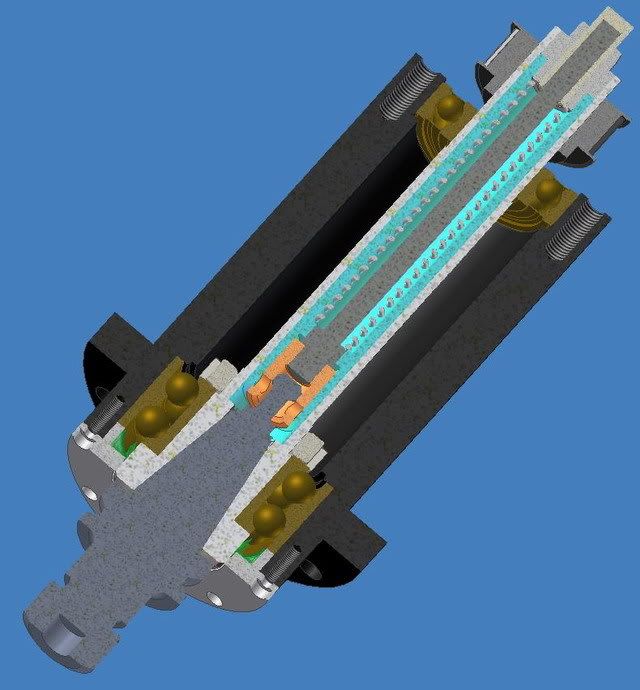
After quite a while researching other spindle projects here, and elsewhere I started to design around a BT30 holder with a 45 degree pullstud. The final design ended up looking like this:
The two lower bearings are angular contact 7207BEGAP and the top bearing is a standard 6206. Allthough I'd love to have "special purpose spindle bearings" I hope that these will be good enough. They are universally matched and ground for a light preload. My aim is to be able to run somewhere between 6000-8000 rpm but we'll see.
There's a coilspring in the drawing but that is of course belleville washers in the real spindle. 114pcs of them provides around 3000N when the taper of the tool holder makes contact with the spindle taper.
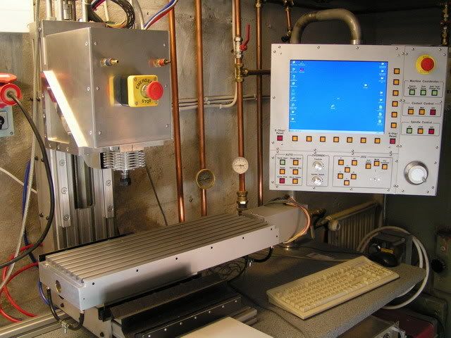
And here's the machine it will hopefully end up on when finished:
I started by making the housing for the spindle. At first I intended to make it out of steel or even stainless but changed my mind and made it out of aluminum. If it turns out to be bad choise I'll either make new one or have one made (I don't want to do it again, see below...) Anyway, here's a couple of photos of the process:
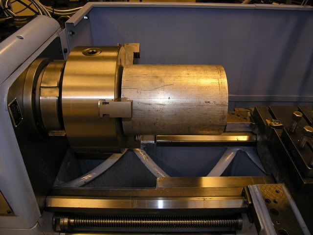
160mm dia aluminum round bar ready for machining:
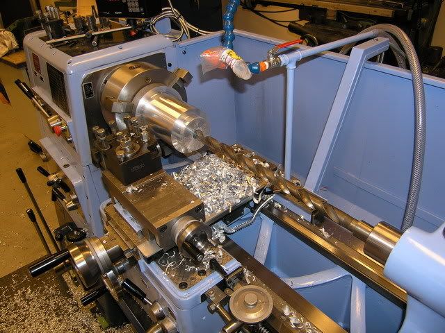
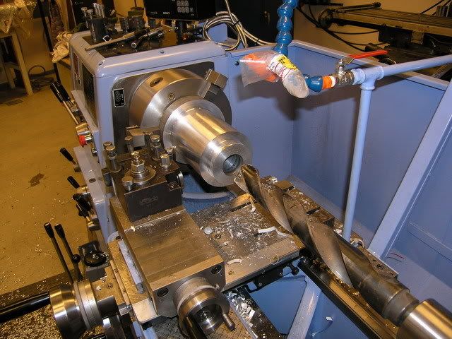
I turned down the outer diameter of the lower part and the flange and then started to drill out the ID:
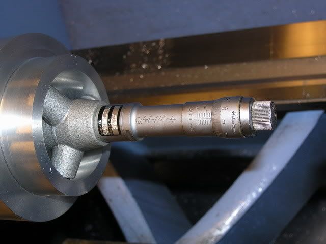
When the bulk of the material was drilled out I machined the seat for the lower bearings, here I'm using a three-point micrometer to measure the diameter - 71.985mm for a 72mm bearing:
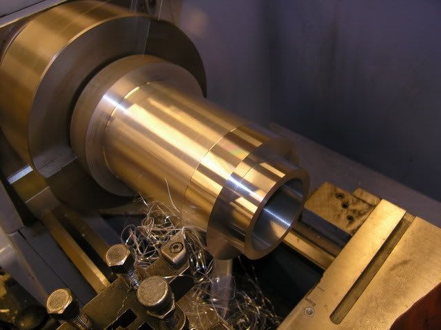
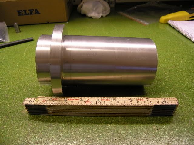
With the lower bearing seat done I brought the OD to its final dimensions 90mm and 125mm for the flange:
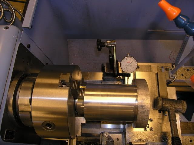
I then made a "plug" that fits in the bore for the lower bearings so that I shouldn't deform the bore when clamping it in the chuck. Then I indicated it as true as I could. I got it to within 0.01mm:
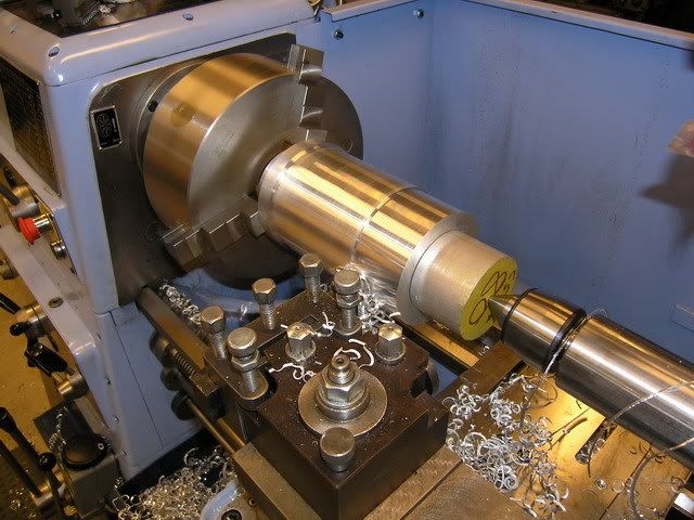
Then I machined off the excess material and made the bore for the top bearing. The live center wasn't big enough to fit in the 62mm bore for the top bearing so I made another plug to use as support while maching the rest of the OD down from 125mm to 90mm:
When I was ready to finish the top end I found that the fit between the top "plug" and bore was a little too tight so I had to remove the whole setup from the lathe in order to remove the plug. When resetting it up I didn't tighten the the chuck enough (I was affraid to deform the lower bearing bore)and the whole housing came loose while finishing off the top end....ouch... It seems to be OK though, time will tell. (You can see the dents from the jaws in the photo)
My intention was to have the housing anodized but with all the uggly marks in it I'll leave it as it is.
That's it for my first post here. More later.
/H.O
Thread: BT30 Spindle project
Results 1 to 20 of 174
Threaded View
-
07-28-2007, 07:17 PM #1
 Registered
- Join Date
- Jul 2007
- Posts
- 887
BT30 Spindle project

 Reply With Quote
Similar Threads
-
BT30 Spindle cartridge for a smithy mill
By mlennon in forum Maintenance DIY DiscussionReplies: 0Last Post: 03-12-2013, 05:13 PM -
Looking for a BT30 Spindle
By xtwalt in forum Uncategorised MetalWorking MachinesReplies: 1Last Post: 11-20-2012, 10:10 PM -
BT30 Spindle
By dirtridn2010 in forum Tormach Personal CNC MillReplies: 0Last Post: 05-07-2012, 11:19 AM -
Reasonably priced BT30 ATC spindle.
By dwalsh62 in forum News AnnouncementsReplies: 0Last Post: 05-12-2011, 05:59 PM -
BT30 taper spindle for mold making
By grantmi1 in forum Hard / High Speed MachiningReplies: 5Last Post: 02-28-2006, 09:41 AM
