


Hi Phil ,
if the board you have is like the one in the first post
you can unplug the EL817 opto-isolator from the socket and connect what was the diodes cathode connector to the transistors collector connector
as in the picture in post 217 on page 19
the wire link shown connects the socket terminals 2 & 4 together
I've only seen the 6N137 used on single axis board http://media.digikey.com/pdf/Data%20...7%20Series.pdf
the faster 6N137 used for the step and direction signals and the EL817 for the enable input if used
if the 6N137 LED is wired the same way with the anode (pin 2) is connected to +5V
you will need a wire a link from terminal 3 to terminal 6
(some detailed pictures of your board could help to trace the connections)
John
Results 621 to 640 of 900
-
10-19-2012, 11:11 PM #621
 Registered
- Join Date
- Mar 2007
- Posts
- 2083
-
10-20-2012, 09:06 AM #622
Registered
- Join Date
- Sep 2009
- Posts
- 14
Thanks, will try that now. It is a single axis board but it seems to have many similarities to the 3 axis boards Originally Posted by john_100


Thanks again, Phil
-
10-20-2012, 12:01 PM #623
Registered
- Join Date
- Sep 2009
- Posts
- 14
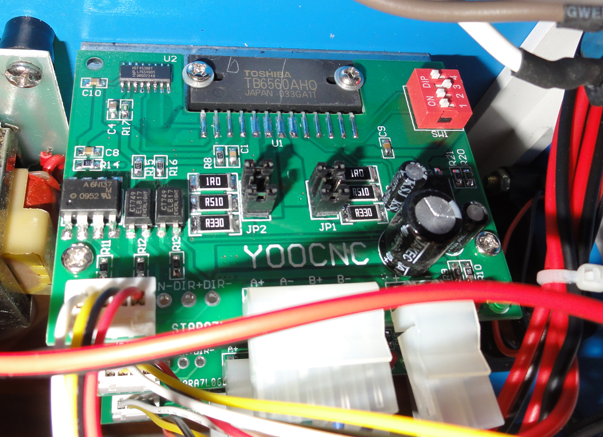
I have some movement now, although it is a bit rough and noisy. I removed the EL817s and movement stopped, but if I bridge them in circuit I have some movement, pic of board attached.
-
10-20-2012, 03:42 PM #624
Registered
- Join Date
- Mar 2007
- Posts
- 2083
Hi Phill ,
from your photo I can see the EL817's are used for the direction and enable inputs
R15 & R16 are 1K pull up resistors connected to the TB6560
If you bypass the 6N137 that isolates the step signal
you will need to check the breakout board can sink 10mA as the pullup resistor R14 is 510 ohms
John
-
10-20-2012, 05:47 PM #625
Registered
- Join Date
- Sep 2009
- Posts
- 14
What I will try to start is put all ICs back on the board and jumper the EL817s, to check what happens. Then I will jump the 6n137 and see what happens. If still no luck I will run the shop and get a battery for my multimeter Originally Posted by john_100
Thanks for the help John
-
10-20-2012, 06:13 PM #626
Registered
- Join Date
- Sep 2009
- Posts
- 14
All ICs are on the board now. With the EL817s jumpered and the 6N137 as it should be, nothing happens, not even an LED blink. If I jumper them all I get ~2mm a sec movement that's very noisy. So I think I will need to replace the 6N137. Is it possible to use a 4N25 as I have them in stock, if so what pin goes where
Thanks
-
10-20-2012, 09:00 PM #627
Registered
- Join Date
- Mar 2007
- Posts
- 2083
Hi Phil ,
if replacing the 6N137 with a wire link didn't work and you now want to remove the link and fit a 4N25
offset the 4N25 and cut or bend the pin 6
so the PCB terminals 1,7 & 8 for the 6N137 are not connected
as in the diagram . (fitting a socket will make things easier)
John
-
10-24-2012, 01:20 PM #628
Registered
- Join Date
- Sep 2009
- Posts
- 14
Hi Jophn, I tried all suggestions but nothing worked Originally Posted by john_100
 Thanks for the help though, I ordered another 6N137 and once fitted it ran perfectly
Thanks again
-
10-30-2012, 09:19 AM #629
Registered
- Join Date
- May 2011
- Posts
- 0
what is the best configuration for this board (motors and power supply), with which it works the best, without any modifications or problems? Sry for eng.(flame2)
I have a red tb6560 3 Axis!
-
11-20-2012, 06:22 PM #630
Banned
- Join Date
- Jan 2006
- Posts
- 156
I have a tb6560-4axis, the blue one. It works fine with mach3 but now I
want to use it with a manual pulse controller and I don't know if the
enable pins are negative or +5v. Perhaps someone knows this and can
let me know before I damage this board.
-
11-22-2012, 01:24 PM #631
Banned
- Join Date
- Jan 2006
- Posts
- 156
Halo, anybody there. I'm sure somebody has the info.
Please share it with me.
-
11-22-2012, 02:25 PM #632
Registered
- Join Date
- Jan 2011
- Posts
- 49
pulse controller
Hello, There is a gentleman on this web site that goes by the screen name ger21 he is very informative and has helped many of us cnc'ers out, look him up he may be able to help you.
-
11-22-2012, 04:52 PM #633
Gold Member
- Join Date
- Jan 2010
- Posts
- 2141
Originally Posted by salzburg
You will not damage the board, whether you apply +5 volts to the enable input or you apply ground to it. The enable input is isolated via a resistor and an optoisolator (and the input from Mach3 is also isolated from that point through a resistor).
According to my reading of the schematics referenced in the post at http://www.cnczone.com/forums/821195-post19.html, and more specifically in the schematic at http://www.cnczone.com/forums/attach...3&d=1283911876, which may or may not be identical to the wiring of your board, the optoisolator for the X-axis enable input (for example) is connected to the DB-15 connector, pin 5, and a low input on that pin will turn on the LED inside the optoisolator, which will turn on the output transistor of the optoisolator, which has +5 volts on its collector and takes its output from the emitter which is connected through a 1K resistor to enable pin 4 of the TB6560. That enable pin also has a 33K pulldown resistor to ground (and according to the TB6560 spec sheet, there is also a pulldown resistor internal to the chip). So my interpretation is that a low input on pin 5 of the DB-15 will result in a high signal on pin 4 of the TB6560.
According to the TB6560 spec sheet, http://www.toshiba.com/taec/componen.../382/27885.pdf, page 4, a high signal on the enable line will enable the driver chip, while a low signal on that pin will turn all outputs off.
So you will need to put a low signal on pin 5 of the DB-15 connector to enable the TB6560 X-axis (and similar for the other axes).
-
11-23-2012, 05:25 PM #634
Banned
- Join Date
- Jan 2006
- Posts
- 156
Thank you guys, I was so afraid of burning up my driverboard. Now I know what to do.
-
12-05-2012, 07:53 PM #635
Registered
- Join Date
- Oct 2007
- Posts
- 24
So called "The Latest 3rd Generation Revolutionary TB6560 Stepper Driver"
This is my first post, so let me introduce my self: I'm another victim of "Buy first, think later" syndrome, I've recently purchased 4 axis TB6560 driver. It is in it's slow way from China, and while preparing to use it I came across this thread.
I still don't know which version I'll get (It's the one in aluminum box which serves as a cooler, as in pictures attached), but surfing the eBay last few days I've seen other version which was not there few weeks ago when I've purchased. Since I can't post link's search Google for 'ebay 3rd generation TB6560' and you'll find it. It says in the product description:
---
The Latest 3rd Generation Revolutionary TB6560 4 Axis Stepper Driver Set (TB4CD-P)
Descriptions:
The latest 3rd generation TB6565 Stepper Driver has been upgraded to the intelligent, professional and industrial-level drive set by re-designing the PCB board, embedding intelligent memory chip(professional version) and upgrading the external manual control tools (control pad and display panel).
Actually, the 3rd generation TB6565 Stepper Drivers have two types of versions, one is the standard version, and another is the professional version. Compare to the standard version, the professional version mainly has two more functions than the standard version, one is the “computer G-code recording function”, and another is the “manual programing function”. Except these two functions, these two types of versions have no other differences.
Firstly, both of these two types of versions have upgraded their PCB boards, the re-designing the PCB board will avoid the TB6560 chip on the board being easily blown as the previous version.
With the embedded intelligent memory chip, the professional version of this 3rd generation 4 Axis TB6565 Stepper Driver can easily record the G-code running on the CNC software (e.g. Mach3, EMC2, KCAM4, etc..) of the computer, and then rerun the recorded G-code to make the stepper motor work without the computer any more.
Furthermore, the upgraded external manual control tools (display panel and control pad) on the professional version can be not only used for manually controlling the stepper motor, but also manually programming the G-code. All the manually Programmed G-code will also be recorded in to the embedded intelligent memory chip, and then we also can easily run the recorded G-code to control the stepper motor. Considering that the computer G-code recording function is enough for all the three axis working without computer, to avoid repeated function, the manual programming function is mainly designed for one axis to make linear motion, therefore, the three axis cannot be manually programmed simultaneously. This function is widely used on working which just need one Axis, such as RBI machine, Conveyor etc.
Lately, both of these two types of versions adopt the totally enclosed optical isolation and bipolar constant-current chopper to insure working at low noise & vibration, and avoid creeping at a low speed. It is very suitable for driving the 2-phase and 4-phase hybrid stepping motors.
In short, the qualities and functions of the new 3rd generation advanced 4 Axis TB6565 Stepper Driver are revolutionized from the previous version. So, we believe that these two types of versions must satisfy different users on CNC DIY.
---
It looks like to me that someone finally redesigned the board to address the issues that were discussed on this thread.
I would like your opinion: Should I hope that this is the version I receive, or you think that there is not much difference at all?
-
12-06-2012, 02:52 AM #636
Gold Member
- Join Date
- Jan 2005
- Posts
- 1695
It is very easy to correct the problems which plagued the previous designs. All that's needed is for them to use proper speed opto couplers, power the optos from a separate 5v supply and put in a simple circuit to sequence the power supplies.
If they claimed they fixed the problem, then I would tend to believe them.
-
12-06-2012, 11:09 AM #637
Registered
- Join Date
- Jul 2006
- Posts
- 6
Reply to itod
While I have only recently finished my machine and do not have many hours of operation using my version of this type of controller, I can report that I have not suffered any of the trials that many of the other users here have detailed. Perhaps I have been extremely fortunate. I also found this thread after ordering my board and dreaded what I was getting into, however through reading the discussions here I do take some simple precautions during start up. I have set up a switching arrangement that isolates the 24volt supply to the controller, I have also placed a home made interface board between my parallel port and the controller which has enabled me to expand my 3 axis board include a 4 axis and use normally closed limits and e-stop circuits. I always make sure Mach3 is running on my Pc and has control of my parallel port and that the e-stop is engaged before I switch power through to the controller.
Well that is my experience so far, I hope you have a similar experience.
-
12-06-2012, 02:37 PM #638
Registered
- Join Date
- Oct 2007
- Posts
- 24
I'm glad you think so. Still don't know if I'll get the 3rd gen version or previous, but I would sure like to know how can one tell the difference. If somebody has an idea what and where to look for, I would be grateful to hear it. Originally Posted by H500
-
12-07-2012, 01:55 AM #639
Gold Member
- Join Date
- Jan 2005
- Posts
- 1695
Why not just order one that claims to have fixed the problems? Originally Posted by itod
Vendors tend to be secretive in order to prevent others from copying their design. You won't know if a new design is any good until someone buy one and do a review.
If you don't mind buying a kit that needs to be soldered together, I know for sure this one is rock solid because I have one:
http://users.skynet.be/ldt/CNC%20ele...THB6064AH.html
It can handle a higher voltage and current than even the best of the tb6560 designs because it uses a superior chip.
-
12-08-2012, 12:53 AM #640
Registered
- Join Date
- Dec 2005
- Posts
- 3
This is a bit late to response. I have this problem when the acceleration settings in EMC is slow. Increasing the acceleration settings in the configuration file so that it doesn't ramp up / ramp down the speed, and I don't see this problem any more. Originally Posted by MalcolmF
-Thanh

 Reply With Quote
Similar Threads
-
Chinese 3 Axis TB6560 & 300oz @ 24V too slow and not enough power
By KallDall in forum Stepper Motors / DrivesReplies: 12Last Post: 09-28-2016, 06:20 PM -
New (red version) of TB6560 chinese driver board
By hspalm in forum Stepper Motors / DrivesReplies: 19Last Post: 02-23-2014, 01:34 AM -
soc-robotics MK4cp OR chinese TB6560 driver
By 24ariel3 in forum Stepper Motors / DrivesReplies: 2Last Post: 04-09-2013, 04:24 AM -
Maximum Voltage with Chinese TB6560
By riphet in forum Stepper Motors / DrivesReplies: 9Last Post: 10-16-2012, 05:29 AM -
Just got my updated super Pid controller
By msimpson99 in forum DIY CNC Router Table MachinesReplies: 13Last Post: 12-22-2010, 10:35 AM
