


Hello!
I would like to tell you about my CNC router that I have started to build a while ago.
Before I have started the build, there was some preparation time when I researched the web, purchased linear slides, ballscrews and electronics and created a design plan. My main intention was to build a router to work with wood, plastics, PCB material and aluminum – typical materials for R/C hobby. While looking for slide rails and ballscrews, I kept in mind that it would be great to have the working area large enough to cut parts from a standard balsa sheet (4*39 inches). With all the rails and ballscrews I managed to get, the working area appeared to be 746*398*108 mm.
The building started for design #3 on 28th of May, 2010 from this pile of metal. Among all the materials at my disposal, steel profile tubes, channel bars and angles seemed the best option – easy to get and to work with.
First, the sides of the base were welded together and drilled.

Sides of the gantry were assembled likewise.
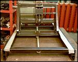
Then gantry sides were preliminary assembled and aligned with gantry bottom using M8 threaded rods.

Such alignment was necessary to adjust threaded plates welded to ends of the pipes properly.
Next step was to weld end plates with threaded holes to profile tubes.
The same procedure was done for the perpendicular base parts.
Plus, the placement of linear slides was marked.
Then it was time for the preliminary assembly and adjustment – a painful procedure that lasted more than a day.
Y-slide base was made from a solid piece of a channel bar.
It was a kind of tricky to drill holes for slides and ballscrew bearings in its horizontal parts.

Z-slide was made from a smaller channel bar.

A number of different flanges for ballscrews and linear bearings were cut from aluminum using a lathe.

Z-slide supposed to be the cylinder slide, so I used 12mm cylinder slides from an old matrix printer. Linear bearings were attached to the slide using aluminum flanges.
Nema23 motor mounts for X and Y motors were welded from channel bars and metal plates. Z-axis motor mount had to be longer than others, so it was made of two pieces of channel bars.

First, I connected them with bolts to achieve the necessary parallelism after welding.

Then I assembled Z-slide, installing the ballscrew and motor mount.

And installed X and Y ballscrews.
Then adjusted the table frame, also made of square profile steel tubes.

And welded it.

Next part was a spindle mount made from a channel bar and a steel plate.

It was very important to weld them carefully to preserve the perpendicularity.

I have installed a BLDC motor as a spindle. Brushless motor is controlled by Mach3 software via a PWM converter.

A small collet adapter was attached directly to its shaft.
Then I have installed cable ducts and drag wires.

At this point the preliminary assembly was complete and I had to disassemble everything, paint steel parts and assemble the router again.
Results 1 to 9 of 9
-
02-11-2013, 09:13 PM #1
 Registered
- Join Date
- Feb 2011
- Posts
- 25
Steel 750*400 Router for Different Materials
-
02-12-2013, 06:18 AM #2
Registered
- Join Date
- Feb 2011
- Posts
- 25
After the disassembly I got two piles of parts – one that had to be painted.
And another – that had not.
While metal parts were drying after the spray-painting
I have used the remaining scrap metal to weld a stand for the router – during the preliminary assembly I realized that it is too large to be placed on my workbench.
This time, while the stand was drying, I started the assembly of the base part of the router.
Once assembled, it was installed on the stand and attached to it with M8 threaded rods.
Installing the gantry, adjusting it with linear slides was this time even more painful. As the gantry was rather heavy, I had to use a winch to lift it and carefully lower it down, to the table and rails.
Also, as you can see on the photo, I have made the sides of the gantry higher by welding profile tubes to them. It was done in order to fully utilize the Z-stroke.
Then Y and Z slides were assembled.
And attached to the gantry.
I have used 282 oz/in. stepper motors to drive all axis.
And connected them to ballscrews using flexible aluminum shaft couplings.
Then installed the table frame, spindle mount, cable ducts and drag chains.
The CNC control system included Pentium-4 PC running Windows XP and Mach3 software, 8” touch-screen monitor and TB6560 4axis driver.
Of course, the router was equipped with end switches for each axis. Electronic and mouse pushbuttons were used for end switches, as they proved to be the more compact and responsive than industrial endswitches available in my city.
The first version of the working table was made of two MDF sheets.
The table was attached to the table frame with bolts.
To protect the CNC system from dust and particles from a working area, a tray made of cellular polycarbonate was installed between the router and the CNC equipment area.
To achieve a proper level of the working table, a Plexiglas plate was installed atop of it and milled. The milling process took several days.
Afterwards, I have started using the router to manufacture the parts for itself. Like motor driver box front panel.
Or flexible coolant hose mounts made of CEM.
Flexible hoses for coolant were attached to the spindle mount.
-
02-12-2013, 12:22 PM #3
Registered
- Join Date
- Dec 2011
- Posts
- 161
Good job, that is some big time welding
 I really like the router, but that base looks super thin compared to the machine!
-
02-12-2013, 01:28 PM #4
Registered
- Join Date
- Feb 2011
- Posts
- 25
Thanks a lot!
The base was temporary, the router just needs a surface to stand on. However, it was welded from a solid armature with a lot of intersections and two horizontal table plates (one of them was never installed) and, in fact, is not so bad. I am planning to get rid of it sometime, but it is only an item in a long queue
-
02-12-2013, 05:44 PM #5
Registered
- Join Date
- Feb 2007
- Posts
- 473
Looks great!
It seems like the 'spindle' is really light-duty compared to the rest of the machine. I would suggest you upgrade to either a trim router or a chinese spindle to get the most out of your machine.
What cutting speeds/rapids can the machine do?Gough Custom - http://goughcustom.com/
-
02-12-2013, 07:30 PM #6
Registered
- Join Date
- Feb 2004
- Posts
- 304
Good work! I agree about the spindle. It's nice to see a machine made out of steel instead of aluminum or MDF once in a while..
-
02-12-2013, 08:30 PM #7
Registered
- Join Date
- Feb 2011
- Posts
- 25
aarongough and kevincnc, You are absolutely right about the spindle! And my story continues
While working with the router I started to note things that had to be improved. First of all, the cheap brushless motor couldn’t handle sufficient loads and soon demonstrated linear backlash of about 0.5mm. I had to enforce the spindle to unload the motor shaft. Also, it was impossible to clamp anything more than 4 mm with a small collet. So, the collet from an automatic lathe supported by two 20mm bearings seemed to me a good idea.
The main problem was that new spindle shaft’s diameter was only 19mm, so I had to lathe a brass bush with 0.5mm-thick walls.
The bush helped to connect bearings and a collet’s shaft.
The plastic bush with slotted hole was then attached atop of the collet.
And a corresponding flat bush was installed at the shaft of a motor.
The motor was connected to a spindle’s case with a brass flange.
As the new spindle was longer than the previous, I had to make a shorter spindle mount.
Finally, the spindle was connected to a mount.
The new 1600Kv motor, however, didn’t show enough torque – it got overheated even while just rotating the heavy spindle with no load.
Another kind of parts I had to replace, were the flexible couplings. Two of them got broken, either from too much torque generated by stepper motors or because of wear. Anyway, I have replaced them with plastic couplings.
Yet another, and I think, most important thing that had to be changed, was the table. The wooden table got deformed after contacts with coolant. Fortunately, I occasionally got a 25mm Plexiglas slab, good enough for a table.
The plate of a proper size was cut with a jigsaw and a manual router.
Then the mounting holes were drilled and the new table was installed to the router.
The router itself was used to drill mounting holes in the table. The table was equipped with polycarbonate walls to prevent cuttings and drops of coolant from escaping the working area. The joints were filled with the oil-resistant sealant to prevent the leak of coolant from the table.
Then the horizontal level of the table was milled using a large end mill.
For now, my CNC router looks like shown on pictures below, the most amount of work is done and the router is able to operate.
Of course, there are still lot of features to be implemented, like fog/mist, coolant circulation, spindle RPM control, 4th axis and so on. I will continue here, when I’ll implement something new.
Concerning the speeds. My current setup is 1000 mm/min for all axis. This feed is maximum for X-axis having microstep of 1/8, Y and Z can move faster, but there is no particular need in it. All the tools that I am using rarely need the feed more than 400mm/min.
I haven't had a chance to measure spindle's maximum RPM. Theoretically, it is around 10000 RPM for 900 Kv motor.
-
02-16-2013, 08:49 PM #8
Registered
- Join Date
- Feb 2011
- Posts
- 25
When I started to assemble the router, I have installed a webcam that shot a timelapse, which was converted to a cartoon, that shows the assembly process. Here it is:
[ame=http://www.youtube.com/watch?v=Yb1AeVqlHeI]CNC Router Assembly - YouTube[/ame]
A long time it took to assemble is compressed in just 80 seconds
-
02-22-2013, 04:21 PM #9
Neuer Benutzer
- Join Date
- Feb 2013
- Posts
- 0
I can not believe it
it is peacedets

 Reply With Quote
Similar Threads
-
examples of materials that can be cut with CNC Router
By limacchina in forum Uncategorised WoodWorking MachinesReplies: 3Last Post: 11-12-2013, 04:52 AM -
CNC router 8x4 For Cutting Multiple Materials
By ciscoe in forum DIY CNC Router Table MachinesReplies: 25Last Post: 02-06-2013, 01:53 AM -
Aluminum - steel rod materials question
By nadsab in forum MetalWork DiscussionReplies: 20Last Post: 05-24-2012, 12:23 PM -
Help with Router Materials and Waste
By wjones in forum DIY CNC Router Table MachinesReplies: 4Last Post: 11-14-2009, 01:36 AM -
CNC router construction materials
By justin22885 in forum DIY CNC Router Table MachinesReplies: 38Last Post: 08-05-2009, 04:36 PM
