


So much of this machine is built from scrap aluminum that was found by rummaging through the scrap bin at work. I purchased some of the larger items like the 3" x 1/2" side plates and the linear bearing extrusions. I got 2 steppers and 3 drives from work that could no longer be used on production equipment but was reported to have worked fine when the machines were disassembled.
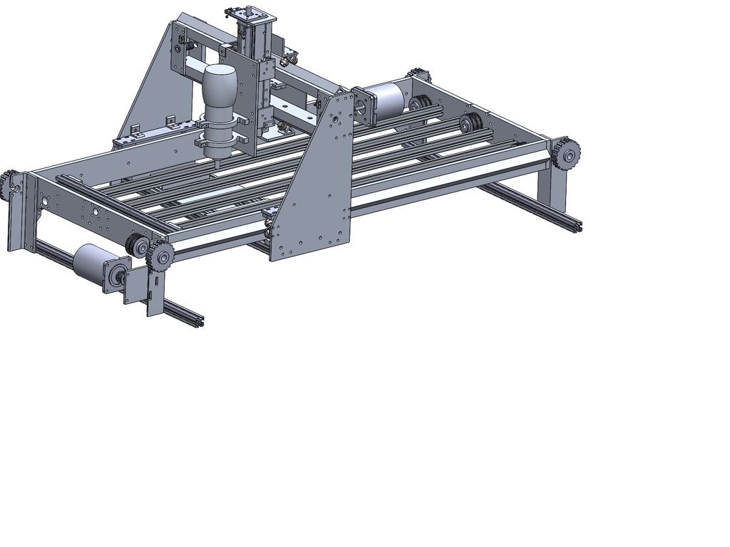
The build volume will be about 20" x 40" x 4"
It uses some 8020 10 series along with some 1/2" aluminum plate. The y-axis side plates are 1/4" 7071 aluminum. I used 8020 gusseted angle extrusion for my linear rails. I may replace this by some proper linear bearing rails in the future but this is working nicely to get me going.
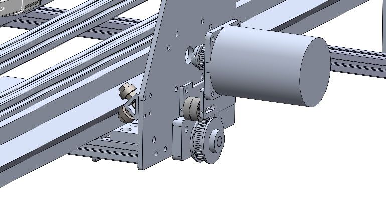
Screws are 1/2-10 single start. The X-axis is geared to a 1:2 increase to make it act like a 2 start. All screws are installed under tension to minimize whipping.
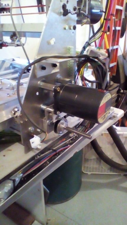
Steppers are Vexta 5 phase. The X and Y are nema 34 and the Z is a nema 23. I tested these out on a table top using the "roadrunner" g-code that comes with Mach3
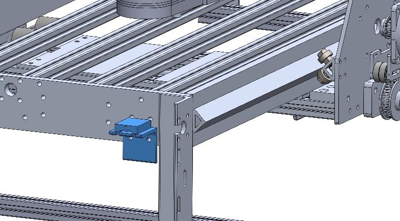
Here are a few pictures of the progress. It started out as a solidworks model:
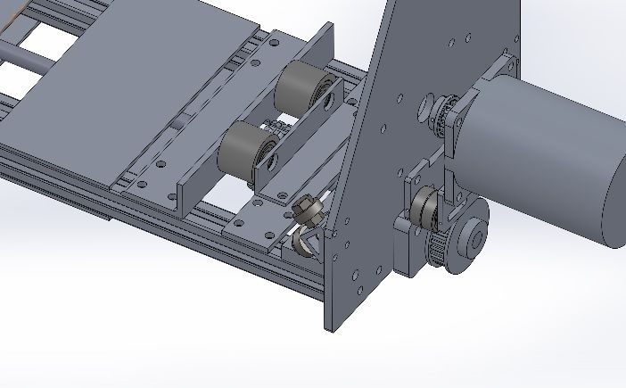
Here is my anti-backlash setup. There's a nice stiff spring between the 2 brass nuts. 1 nut is bolted to the extrusion that they are housed within.
Look at the lovely kite that I machined.... Anyway, Here's what it looked like while I was using it as a manual router "mill" It came in quite handy in this configuration
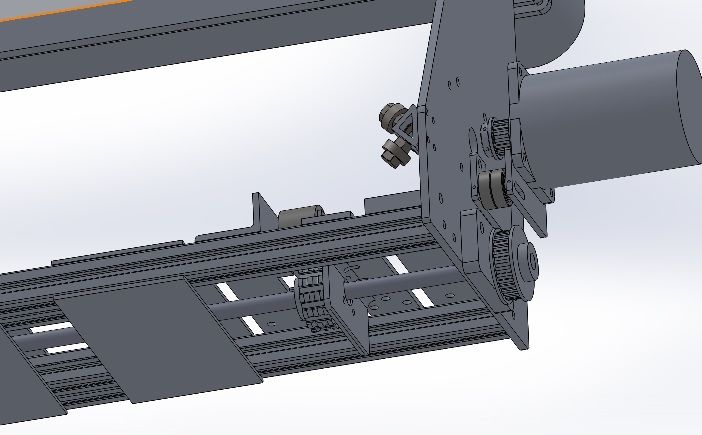
Here's the Y and Z axis assembly without the side plates
This is the bearing assembly that I made. Based on the "buildyourcnc.com" book build but a bit better with that extrusion
I picked up a variable speed dewalt for my "spindle" It will be powered from the control box so that Mach 3 can turn it on and off.
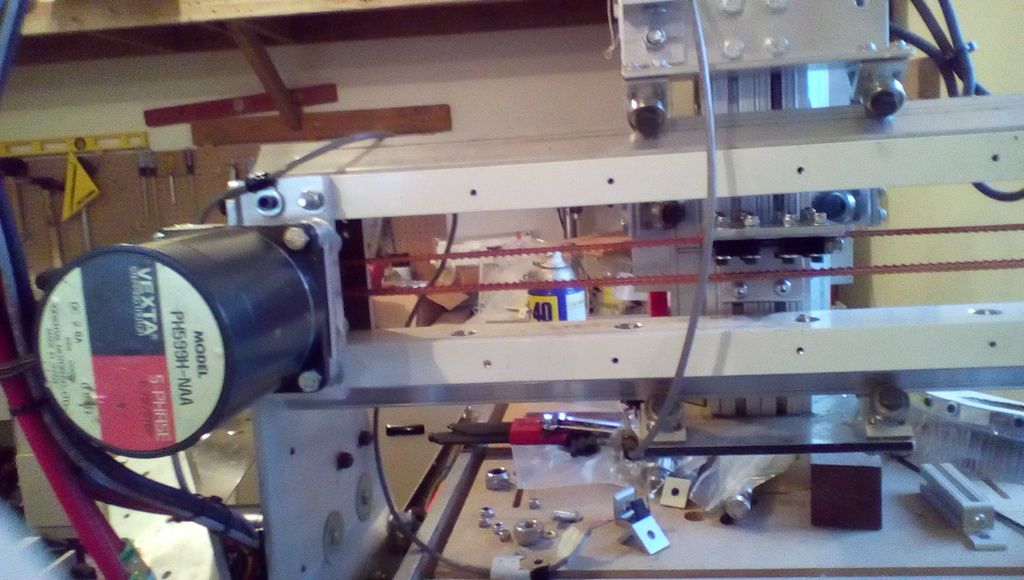
An early version of my belt drive on the X-axis. The tension arms were replaced with something that worked a bit better
Fitting up the X axis motor
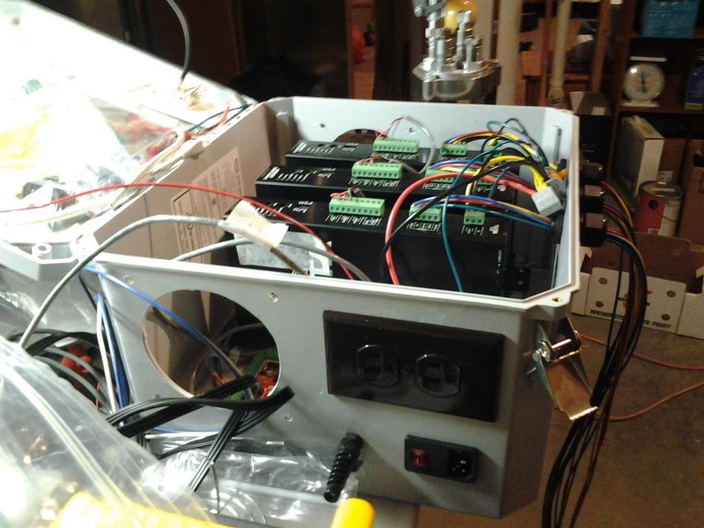
The control enclosure about a week ago. I have it about wired up now but need to clean up my wiring. The outlet on the side is turned on via a solid state relay that can be tripped from the breakout board. The power for that outlet runs through the normally closed side of the e-stop so that it will have a hard shut down as well when the e-stop is tripped. A breakout board input will be on the normally open side of the switch. there's a blue LED to indicate that the switch is not pressed. I'm running a network cable from the BOB through a cord grip that will run to the limit switches. A pendant that came with the BOB goes through a phone jack on the side of the box.
Results 1 to 20 of 20
-
09-03-2014, 07:10 PM #1
 Registered
- Join Date
- Sep 2014
- Posts
- 30
Eric's 3-axis machine from scrap and scavenged parts
-
09-05-2014, 02:25 PM #2
Registered
- Join Date
- Sep 2014
- Posts
- 30
Re: Eric's 3-axis machine from scrap and scavenged parts
The control enclosure is a bit more complete. I may do a bit of cable management and need to add some filtration. A little larger box would have allowed for some much nicer cable management here. BTW, wago wire nuts are awesome....
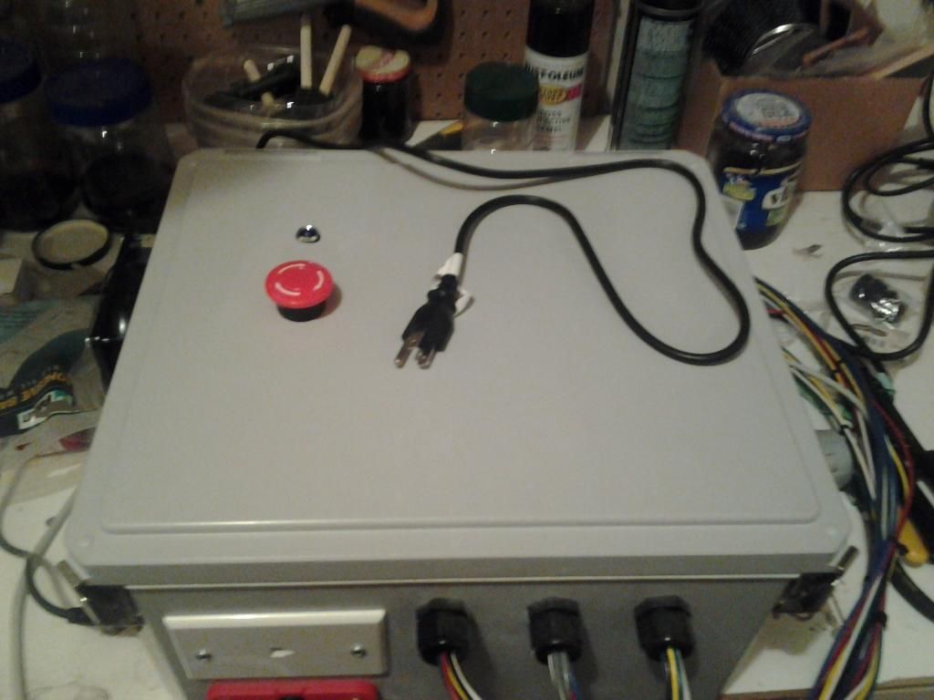
I 3d printed a 2 piece bezel for my DB25 cable pass through that worked out quite nicely. I would have preferred to have the fan in the box, but I was running out of space in there.
-
09-05-2014, 05:23 PM #3
Gold Member
- Join Date
- May 2005
- Posts
- 3920
Re: Eric's 3-axis machine from scrap and scavenged parts
Nice!
Like you I visit the scrap bin every day I'm at work. Unfortunately most of the scrap isn't exactly usable for machine builds but I'm getting there.
-
09-10-2014, 04:51 PM #4
Registered
- Join Date
- Oct 2006
- Posts
- 84
Re: Eric's 3-axis machine from scrap and scavenged parts
Can you upload the pics? They aren't showing up for me.
-
09-10-2014, 05:00 PM #5
Registered
- Join Date
- Sep 2014
- Posts
- 30
Re: Eric's 3-axis machine from scrap and scavenged parts
Here are a few. The other pictures are on photobucket
-
09-10-2014, 05:11 PM #6
Registered
- Join Date
- Jun 2012
- Posts
- 817
Re: Eric's 3-axis machine from scrap and scavenged parts
Steppers look bigger than the spindle!
 That's gonna take one heck of a power supply.
-
09-10-2014, 05:30 PM #7
Registered
- Join Date
- Sep 2014
- Posts
- 30
Re: Eric's 3-axis machine from scrap and scavenged parts
The steppers and drives were free

well, I had to buy one stepper, but they were ditching 2 motors and 3 drives at work and I snatched them up. I was told they work fine, just aren't supported anymore.
And the drives for this one have the power supplies built in. They hook right up to 110AC power.
-
09-11-2014, 01:50 AM #8
Registered
- Join Date
- Jun 2012
- Posts
- 817
Re: Eric's 3-axis machine from scrap and scavenged parts
 Originally Posted by muttstang

Well that's handy. Free is a good price, especially since they are a matched system already.
-
09-11-2014, 01:52 AM #9
Registered
- Join Date
- Sep 2014
- Posts
- 30
Re: Eric's 3-axis machine from scrap and scavenged parts
Yep, and they are plenty big that I could use them on a much larger system in the future with some multi start screws
This one is big enough to build guitar bodies/necks and some other fun stuff!
-
09-12-2014, 03:15 AM #10
Registered
- Join Date
- Sep 2014
- Posts
- 30
Re: Eric's 3-axis machine from scrap and scavenged parts
Got the enclosure up on the wall and the computer is out in the garage. I've got some major cleaning to do! There are several cross braces to put in yet and I still need to get the spoil-board in. Then there's wiring. I have a .050" thick piece of ABS that is 2" wide and several feet long that I'm going to use for a cable drag along the x-axis. The Z axis will have a piece of reinforced 3/8" OD push to connect tube that I will zip tie the wires to. With 3 kids 5 and under there's not a ton of time to work on this thing!
-
09-22-2014, 02:01 AM #11
Registered
- Join Date
- Sep 2014
- Posts
- 30
Re: Eric's 3-axis machine from scrap and scavenged parts
o I hooked the control box up quick. Wiring still needs to be finished but I was able to run a few jogs with the hand controller. Kinda cool!!!!
DSCN4371 - YouTube
-
09-24-2014, 03:08 PM #12
Registered
- Join Date
- Sep 2014
- Posts
- 30
Re: Eric's 3-axis machine from scrap and scavenged parts
Some more wiring in place. wire ties are loose and wires are not in tight yet as I still have to run my limit switches. I haven't quite figured out the brackets for that yet
-
09-30-2014, 04:02 AM #13
Registered
- Join Date
- Sep 2014
- Posts
- 30
Re: Eric's 3-axis machine from scrap and scavenged parts
doh, broke a 4-40 tap....
got 4 out of 6 limit switches installed. going to have to figure out what inputs those correspond to on the USB part of the BOB
-
10-05-2014, 04:04 AM #14
Registered
- Join Date
- Sep 2014
- Posts
- 30
Re: Eric's 3-axis machine from scrap and scavenged parts
woot, the limit switches are hooked up and work. I need to get the relay for the router set up and then button up the wiring and install the spoilboard
-
10-13-2014, 03:52 AM #15
Registered
- Join Date
- Sep 2014
- Posts
- 30
Re: Eric's 3-axis machine from scrap and scavenged parts
Made my first cuts today
A big ruler to measure the boys as they grow up. Got the machine running pretty slow at the moment. I really want some multi start screws on the X axis now!! I get a bit of whipping with it as it sits if I crank the speed up too much.
CNC router in action - YouTube
Kept it simple for the first thing made.
-
10-18-2014, 03:09 AM #16
Registered
- Join Date
- Sep 2014
- Posts
- 30
Re: Eric's 3-axis machine from scrap and scavenged parts
I printed up some new idlers (the other ones wobbled badly) and it really reduced the movement of the screws. I should be able to bump up the speed quite a bit
-
10-27-2014, 01:53 PM #17
Registered
- Join Date
- Sep 2014
- Posts
- 30
Re: Eric's 3-axis machine from scrap and scavenged parts
Already cut my first piece of fixture over the weekend.... Thankfully it was just a chunk of 1/4" washer that was holding down the edge of the work piece. Lesson being to be sure of you workpiece zero position!
-
05-18-2015, 09:51 PM #18
Registered
- Join Date
- Sep 2014
- Posts
- 30
Re: Eric's 3-axis machine from scrap and scavenged parts
I scored some more stuff from the shop at work. They were throwing out some timing belt and pulleys. Stuff from WB-Berg. A .5" pitch belt for the X axis with a .2" pitch belt on the Y-axis. I'll eventually convert the Z to a ballscrew but this ought to really speed up my machine. I'm running 1/2"-10 single start acme screws right now and really have to spin them fast to get 50 ipm.
Here's what I'm looking to do. It should fit nicely and actually clean up the footprint on my machine. It will have a belt on both sides of the bed for the X-axis and I'm going to double up the belts on the Y-axis to minimize stretch.
-
06-04-2015, 02:29 PM #19
Registered
- Join Date
- Sep 2014
- Posts
- 30
Re: Eric's 3-axis machine from scrap and scavenged parts
So after checking the belt length, but regretfully not before making a bunch of brackets, I found that the X-axis belt wasn't long enough to do both sides with the design above so I'm moving the motor to the gantry.
So here's the 3d model of the X-axis motor on the gantry. I have most of the parts finished for it and need to buy one more pulley as I only have 1 right now. I'm doing a 2:1 speed reduction off of the motor. At 100 IPM I should get around 90 lbs of force on the X-axis and around 50 lb on the Y-axis. Should be plenty for this smaller machine. I'm running the belt where the X lead screws use to run and through the mounting hole for them. That way I can adjust tension and position from the ends of the machine easily.
The Y-axis belt is installed and needs to be tensioned but that's easy to do with a short piece of 8-32 threaded rod. Then I will tighten down the clamps and install the motor.
This one shows the jack shaft and one of the pulleys from the bottom of the gantry:
Here is the idler pulley configuration. They should line it up nicely with the belt clamps on the end of the machine. The 0.5" pitch Flex-e-grip belt is rated for around 300 lbs and has a pair of 1/16" steel cables through it so there shouldn't be a whole lot of stretch.
And this is what the X-axis belt clamps look like
-
06-10-2015, 02:05 PM #20
Registered
- Join Date
- Sep 2014
- Posts
- 30
Re: Eric's 3-axis machine from scrap and scavenged parts
Here's the side of the gantry with the x-axis motor mounted:
Y-axis motor and the belt configuration
And the Y-axis motor mounting


 Reply With Quote


Similar Threads
-
Machine scrap yard in Seattle area?
By Darren_T in forum DIY CNC Router Table MachinesReplies: 9Last Post: 05-14-2011, 10:16 PM -
Thanks to Eric @ Tormach
By tikka308 in forum SprutCAMReplies: 0Last Post: 12-06-2010, 08:55 PM -
Help me with this scavenged motor please
By lagfish in forum Servo Motors / DrivesReplies: 3Last Post: 01-25-2008, 06:13 PM -
Scavenged Transformers - Amp Rating?
By cbcnc in forum CNC Machine Related ElectronicsReplies: 13Last Post: 06-30-2004, 03:32 AM
Tags for this Thread
071,
287,
422,
8020,
aluminum,
axis,
bearing,
belt,
belt drive,
control,
diy cnc router table machines,
down,
enclosure,
extrusion,
g-code,
goes,
http:,
indicate,
linear,
lovely,
mach 3,
manual,
mill,
not,
nuts,
plates,
production,
router,
side,
solidworks,
spindle,
steppers,
table,
within,
work,
[img
