


hi
did anyone use a pneumatic cylinder for balanced z axis ?Attachment 261240
Results 1 to 20 of 26
-
12-18-2014, 08:23 PM #1
 Registered
- Join Date
- Dec 2009
- Posts
- 24
z axis balanced whit pneumatic cylinder
-
12-18-2014, 11:29 PM #2
Member
- Join Date
- Apr 2004
- Posts
- 5752
Re: z axis balanced whit pneumatic cylinder
If you mean a gas strut, yes, I've done it. It works a lot better than the constant-force springs I tried first, that kept breaking.
-
12-19-2014, 04:35 AM #3
Registered
- Join Date
- Aug 2011
- Posts
- 999
Re: z axis balanced whit pneumatic cylinder
possible with a normal cylinder but too complicated with regulated air supply. I just use a gas spring (like for your car's hood) and that is simple, cheap and worked fine for me the last 2 years. Never noticed the additional damping effect and that may be beneficial, anyway.
Box Joint and Dovetail CAM software here: WWW.TAILMAKER.NET
-
12-19-2014, 05:56 AM #4
Registered
- Join Date
- Dec 2009
- Posts
- 24
Re: z axis balanced whit pneumatic cylinder
dear JerryBurks
thanks for your advises,i test whit gas spring and it working well ..but i cant find a best brand at my country then after 2 or 3 month it damage for bad quality
so i want do it whit pneumatic air cylinder and regulator if you have a plan make me happy.
thanks
-
12-19-2014, 06:02 AM #5
Community Moderator
- Join Date
- Dec 2003
- Posts
- 24220
Re: z axis balanced whit pneumatic cylinder
If you use pneumatics you require a constant pressure balancing valve, otherwise pressure will build on the downward stroke.
Al.CNC, Mechatronics Integration and Custom Machine Design
“Logic will get you from A to B. Imagination will take you everywhere.”
Albert E.
-
12-19-2014, 06:34 AM #6
Registered
- Join Date
- Dec 2009
- Posts
- 24
Re: z axis balanced whit pneumatic cylinder
hi Al_The_Man
please check this image, i draw it ..
is it correct?
-
12-19-2014, 06:33 PM #7
Registered
- Join Date
- Nov 2011
- Posts
- 205
Re: z axis balanced whit pneumatic cylinder
Add an accumulator to increase the cylinder volume to avoid the problem. Originally Posted by Al_The_Man

Don
-
12-19-2014, 08:16 PM #8
Community Moderator
- Join Date
- Dec 2003
- Posts
- 24220
Re: z axis balanced whit pneumatic cylinder
My Knee mills use the constant pressure valve on the Knees, as they are motor operated.
Al.CNC, Mechatronics Integration and Custom Machine Design
“Logic will get you from A to B. Imagination will take you everywhere.”
Albert E.
-
12-19-2014, 09:51 PM #9
Gold Member
- Join Date
- May 2005
- Posts
- 3920
Re: z axis balanced whit pneumatic cylinder
An air cyclinder can last a very long time in this sort of application. If the cylinder is rebuildable, that is you can replace the seals, you can get many years of useful life. As Al said above you need to use a pressure regulator that can compensate for the pressure increase as the cylinder is driven down. Your local pneumatics supplier should be able to hook you up. Originally Posted by omid_king
This approach is fairly common on commercial machinery. I know some of the gantry based extractors at work counter balance the vertical axis this way. The method is reliable and fairly easy to implement. Obviously it does require shop air but that is common in most manufacturing settings.
-
12-19-2014, 09:54 PM #10
Gold Member
- Join Date
- May 2005
- Posts
- 3920
Re: z axis balanced whit pneumatic cylinder
Originally Posted by omid_king
Yes, that is the basic idea. The trick is to buy the right pressure regulator. There are two issues really with the regulator. It needs to support the flow rate required and it needs to "unload" the pressure as the cylinder piston is pulled down.
-
12-20-2014, 05:27 AM #11
Registered
- Join Date
- Dec 2009
- Posts
- 24
Re: z axis balanced whit pneumatic cylinder
this is point ( needs to "unload" the pressure as the cylinder piston is pulled down) Originally Posted by wizard
now how can do it?! because regulator have a single way just adjust pressure
-
12-20-2014, 05:01 PM #12
Community Moderator
- Join Date
- Dec 2003
- Posts
- 24220
Re: z axis balanced whit pneumatic cylinder
There is a particular constant pressure balancing valve that is specific for this purpose, you would need to contact a supplier or find a source in your area.
Al.CNC, Mechatronics Integration and Custom Machine Design
“Logic will get you from A to B. Imagination will take you everywhere.”
Albert E.
-
12-21-2014, 09:39 PM #13
Gold Member
- Join Date
- May 2005
- Posts
- 3920
Re: z axis balanced whit pneumatic cylinder
One extreme expense wise would be something like this: http://www.pneumaticcounterbalance.c...3-06-0112E.pdf. Originally Posted by omid_king
You should be able to find an all mechanical solution good enough for this sort of usage though. Your best bet is to find a local specialist in the supply of pneumatic controls in your area. A good supplier should be able to hook you up with a regulator with the required functionality. You really don't need the fancy electronic controls linked to above.
-
12-22-2014, 12:30 AM #14
Registered
- Join Date
- May 2014
- Posts
- 182
Re: z axis balanced whit pneumatic cylinder
I sketched up what the ideal pneumatic assist might look like with a reservoir.
You'll want some controls in place to operate the system - ideally you would use a pressure sensor on the accumulator to determine a high location and shut down the compressor when it is reached and a low pressure state where you require more pressure and the compressor turns on. If you size your components right, then your duty cycles will be appropriate and you will increase your compressor life. If not, you could burn out your compressor faster.
You'll require a 3 way valve if you just need force during moves against gravity. It wouldn't be a bad idea to have another 2 way valve in front of the precision regulator just to not waste air. Precision regulators bleed air off if the pressure is too high to achieve the desired pressure.
It's going to be tougher to package, but if you can orient the air cylinder as shown in the diagram then you will get more bang for the buck. The rod of the cylinder takes up surface area on the piston, if you push with the same pressure on the opposite side of the rod, you get a greater force.
-
12-22-2014, 06:56 PM #15
Registered
- Join Date
- Dec 2009
- Posts
- 24
Re: z axis balanced whit pneumatic cylinder
thank you so much... this is helpful to me Originally Posted by UA_Iron
-
12-22-2014, 07:16 PM #16
Registered
- Join Date
- May 2006
- Posts
- 27
Re: z axis balanced whit pneumatic cylinder
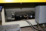
I have had an air assist cylinder on my machine for a few years now on my retrofitted Masterwood Speedy 207. It works perfectly. I have an air tank under the machine with an adjustable pressure regulator that regulates the cylinder.
Photos from a few years ago.
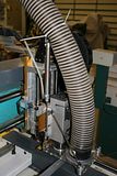
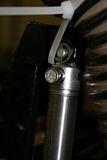
https://www.youtube.com/watch?v=SbFs-Ofb7v8
-
12-22-2014, 07:28 PM #17
Registered
- Join Date
- May 2006
- Posts
- 27
Re: z axis balanced whit pneumatic cylinder
Duplicate post.
-
12-22-2014, 08:09 PM #18
Registered
- Join Date
- Dec 2009
- Posts
- 24
Re: z axis balanced whit pneumatic cylinder
bodini great ! you do nice job ,congratulation and thanks for share to all...
i want to do like this
-
12-23-2014, 02:06 AM #19
Registered
- Join Date
- Nov 2011
- Posts
- 205
Re: z axis balanced whit pneumatic cylinder
Is the tank the supply tank (before the regulator) or an accumulator for the cylinder? Originally Posted by omid_king
Don
-
12-23-2014, 02:29 AM #20
Registered
- Join Date
- May 2006
- Posts
- 27
Re: z axis balanced whit pneumatic cylinder
Its plumbed like this: Input>check valve>tank>filter>regulator >cylinder. Originally Posted by DonKes
The onboard tank was used so that I do not have to have the air from the compressor hooked up if it becomes unavailable. I see it as a $40 insurance policy (or whatever I paid for it.) That's why it has a check valve on it.
The first time I ran air to it, I adjusted the regulator so that (when unpowered) the spindle would stay up when unpowered. That happens to be about 90 psi on this machine. When unpowered, the Z does not move up or down (position read by encoder). The timing belt that runs the leadscrew can be turned with little effort in either direction with about equal force.
I got the idea for this when I read that some industrial machines use a high pressure nitrogen charged assist. Its worked very well for me.

 Reply With Quote


Similar Threads
-
Mounting wax cylinder to 4th axis
By MarcusWolschon in forum Material Machining SolutionsReplies: 6Last Post: 04-06-2014, 07:10 AM -
V25 : 4 axis wrapping for text on a cylinder
By aldepoalo in forum BobCad-CamReplies: 11Last Post: 11-29-2013, 06:33 PM -
Wiring in an air cylinder controller with 1 Axis
By glomagno in forum CNC Machine Related ElectronicsReplies: 12Last Post: 12-17-2012, 02:29 PM -
Pneumatic Air Cylinder questions
By Goldhunter_2 in forum MetalWork DiscussionReplies: 39Last Post: 10-11-2012, 03:30 PM -
4th axis cutting on a cylinder
By 660limited in forum MastercamReplies: 1Last Post: 07-30-2009, 12:21 PM
