


OK, I think I have this figured out now. The tl;dr is that I think I have the wiring correct as shown in the picture of my original post.
Here's the nitty gritty of why I think I have it correct. I had to get out the multimeter and check continuity between some things to make sense of it.
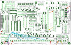
1. In the attached picture, all arrows of the same color are points which are common to one another (0Ω).
2. The power terminal at the bottom, marked with the orange and gold arrows, is tied to the +5v and GND pins on that big chip on the board. Based on that, I'm asserting that this should be fed by the PC +5v.
3. The power terminal at the right, marked with the purple and red arrows, is tied to +5v and GND pins that go with the IO pins of the breakout board itself. The jumper which decides whether your 4 axis COM pins (lines in blue) are GND or +5v is also tied to the same place. Based on that, I'm asserting that this should be fed by the machine's +5v power supply.
I feel pretty confident about it now, but if someone in the know disagrees, I'd love to hear. (Does Arturo Duncan from cnc4pc lurk in these forums?)
Results 1 to 10 of 10
Threaded View
-
05-24-2015, 02:23 AM #4
 Registered
- Join Date
- Mar 2015
- Posts
- 17
Re: C11T Breakout Board Power, 5v and 12v. Did I get it right?

 Reply With Quote
Similar Threads
-
c10 breakout board losing power when parallel cable pluged in.
By carnagex in forum CNC Machine Related ElectronicsReplies: 3Last Post: 01-19-2014, 07:22 PM -
Fried C11T board??
By eartaker in forum Benchtop MachinesReplies: 15Last Post: 04-21-2011, 08:11 PM -
How to wire my motors power supply and controllers with breakout board
By madaxe in forum CNC Machine Related ElectronicsReplies: 6Last Post: 05-01-2010, 12:30 PM -
Breakout Board, Driver and Power for nema23 - UK supplier?
By mnbylcr2 in forum Benchtop MachinesReplies: 4Last Post: 05-21-2009, 05:47 PM -
Breakout board - power light indicator?
By MakotoKamui in forum Automation Technology ProductsReplies: 3Last Post: 03-24-2008, 05:45 PM
