


Hi,
I'm cross-posting this everywhere because I need a lot of replies fast.
I'm nearly done with a G201/G210/G202/G212 replacement design called the G203 for right now. It is a complete, clean-sheet CPLD based new circuit. Same size and pinout as the G201 drive but a whole lot of new features.
Here's where I need input. The G203 uses 3.3V logic which makes the step/direction opto-isolator interface work with much lower current. The quandry:
1) Be 100% backwards compatible with the existing drives. That means supplying +5VDC to the COMMON terminal and require 5VDC step/direction signal levels. The G203 would keep an unplug and replace compatibility with our current drives.
2) Change the COMMON terminal spec from +5VDC to GND. The G203 requires only 2mA max to operate step/direction optos instead of 16mA. The G203 has a max step pulse frequency of 350kHz (>10,000 RPM on a 1.8-degree motor) without any funny G201 step/direction timing restrictions.
The result is supply step, direction and PC ground to the G203 and it will run. It will work now with 3.3V or 5V logic; no level-shifting breakout boards are required, no +5VDC supplies.
Please let me know: Option (1) or option (2). The first 1,000 boards must go to the PCB fabrification house Monday.
Mariss
Thread: Geckodrive user input requested
Results 1 to 20 of 35
-
07-06-2006, 04:16 AM #1
 Gold Member
- Join Date
- Mar 2003
- Posts
- 2839
Geckodrive user input requested
-
07-06-2006, 04:23 AM #2
Gold Member
- Join Date
- Jun 2003
- Posts
- 2103
Mariss is the last paragraph attached to the 2nd option? If so, my vote is #2 Originally Posted by Mariss Freimanis
if fact my vote is #2 anyway!
MikeNo greater love can a man have than this, that he give his life for a friend.
-
07-06-2006, 04:30 AM #3
Gold Member
- Join Date
- Mar 2003
- Posts
- 2839
Yep; it is.
I have been torture testing a hand-built SMT prototype for the last week. It works so good that only minor changes were required on the PCB gerber files. Blows the G201 clean away.:-)
Mariss
-
07-06-2006, 04:41 AM #4
Gold Member

- Join Date
- Jun 2003
- Posts
- 3312
I'd also suggest #2, backwards compatability isn't that important in this minor of a wiring change. You'll have less support issues, more satisfied customers...
Phil, Still too many interests, too many projects, and not enough time!!!!!!!!
Vist my websites - http://pminmo.com & http://millpcbs.com
-
07-06-2006, 05:01 AM #5
Gold Member
- Join Date
- Mar 2003
- Posts
- 2839
The 3.3V thing with new PCs has been a real headache. Some of our drives "sort of work" with them, others flat-out do not. Both kinds are being operated completely out of spec.
The typical support exchange for this begins with "I got 3 of your drives. One works, the other 2 don't. What's wrong with them?". Well, what's wrong is they are not designed to work with 3.3V signals. Some may, most won't.
Normally I stick with 100% backwards compatibility with any new design but this 3.3V/5V thing is a real and growing headache. It's very tempting to completely make it all go away using option 2.
Mariss
-
07-06-2006, 05:17 AM #6
Registered
- Join Date
- Jan 2005
- Posts
- 746
There is something to be said for keeping things the same for the ease of "plug and play". Since your headaches stem from the use of 3.3v logic in todays computers and there will be more of them to come. It's not hard to move a few wires around if you need to replace an older drive. I vote for option #2.
You already provide a quality drive for a good price with an excellent reputation. It would be hard to improve on a good thing except for trying to make it more idiot proof. Heck, I thought it was idiot proof already.If it's not nailed down, it's mine.
If I can pry it loose, it's not nailed down.
-
07-06-2006, 05:25 AM #7
Registered
- Join Date
- Jan 2005
- Posts
- 111
Mariss: I hope to soon be a new customer. How do the two options relate to using the drive with the Grex? Planning Mach3/Grex plugin, Grex, 5 stepper drives, Compaq laptop computer is that doable with the new drive?
Thanks
Dave
-
07-06-2006, 05:33 AM #8
Gold Member
- Join Date
- Mar 2003
- Posts
- 2839
ROHS compliance and the growing unavailabilty of 4000-series CMOS logic has promted this design. I'm a lazy person who is loathe to fix something that isn't broken.:-) I have read the handwriting on the wall however and it says "Design a new drive series if you still want to be here in 5 years".
The G201 traces its ancestry back to 1985 so it's been a good run but it's time to move on. The G201 will be in stock and available for at least the next 3 to 5 years. We intend to choke G201 demand by pricing the replacement at parity while offering significant performance enhancements once the production teething problems are overcome.
Mariss
-
07-06-2006, 05:35 AM #9
Registered

- Join Date
- Aug 2003
- Posts
- 327
Mariss
Option 2 is the only way to go. At the moment people running G201's already understand how the unit works. People who don't have one are finding it hard to wire up (as i did when I got one).
Make a product as idiot proof as possible in my opinion
/Michael (an idiot)
-
07-06-2006, 05:37 AM #10
Gold Member
- Join Date
- Mar 2003
- Posts
- 2839
It has no impact on the G-Rex since both GND and +5VDC is available in each axis connector group:
+5VDC
GND
STEP
DIR
CH_A
CH_B
CH_I
LIM
Mariss
-
07-06-2006, 06:34 AM #11
Gold Member
- Join Date
- Mar 2003
- Posts
- 2839
They always make better idiots though.:-)
1) The G203 uses a lossless (no current shunt resistor) short-circuit detect/protect circuit that senses top MOSFET drain-to-source "on" voltage, level-shifts it to ground reference and trips a protection latch if it is excessive (>10A).
2) No internal jumper settings at all:
2A) The G203 covers a 0A to 7A range instead of 1A to 7A.
2B) The G203 goes into a motor heat reducing recirculating switch mode when the motor is stopped while maintaining full holding torque.
2C) Auto-gain adjust for NEMA-42 anti-resonace.
2D) No external capacitor needed at currents above 3A. A ripple current canceling design takes most of the stress off of the internal 100uF/100V cap.
2E) No weird G201 step/direction timing constraints. Simply have the direction input true before the active step pulse edge. It's clocked in now.
2F) Opto-isolated DISABLE input. Run it from your PC if you wish just like step/direction. DISABLE free-wheels the motor and clears the short-circuit protect latch.
2G) A green "POWER" LED and a red "FAULT" LED. This eliminates the G202/G212 quandry of "Why isn't it running? Is it short-circuit or is it something else?".
2H) Over-temperature protect. You just can't burn it down if you forgot to put it on a heatsink while you are running your 7A motor at 80VDC. It shuts down into FAULT when the board temp reaches 105C.
2I) Still trying to decide on this: An internal fuse that blows if you:
a) Put more than 114VDC on the G203 power supply input terminals.
b) Apply reversed power supply polarity (Get '+' and '-' all mixed up).
c) Something inside goes very badly south.
Problem is the fuse would be a thru-hole soldered-in PicoFuse. You blow it and the drive has to come back for replacement unless you are a really good electronics type person with really good multi-layer board rework skills in which case you wouldn't have blown the fuse in the first place.:-)
2J) Top-side adjustable ADJUST trimpot. You won't believe the number of requests for this.
---------------------------
Again, a completely new clean-sheet 2006 design, not another evolution of the G201. The G203 has only 2/3 the number of SMT parts so we can turn out half again as many a day as G201s. That means 450 a day instead of 300.
Downside is a CPLD is a programmable device and each must be JTAGed which takes 15 seconds. Doesn't seem like much? That's 6,750 seconds or nearly 2 hours; a quarter of a work day.
We need to see how the "upside" and the "downside" balance out. I'm hoping for a draw in 3 months. That will affect the price.
Mariss
-
07-06-2006, 06:47 AM #12
Registered
- Join Date
- May 2006
- Posts
- 1469
Mariss is it possible to have protection built in so that if someone swaps in a
new drive without changing the necessary wiring it won't blow up")
Be good if it just doesn't work rather than have a disaster :cheers:
-
07-06-2006, 07:37 AM #13
Registered
- Join Date
- Jun 2005
- Posts
- 476
Mariss, #2 is the obvious choice for new users, and old users who have mounted their geckos individually. However, will this cause problems for users with the PMDX motherboards?
Even so, I think #2 is going to be the best compromise.
-
07-06-2006, 04:17 PM #14
Community Moderator
- Join Date
- Mar 2003
- Posts
- 35538
#2
Gerry
UCCNC 2017 Screenset
http://www.thecncwoodworker.com/2017.html
Mach3 2010 Screenset
http://www.thecncwoodworker.com/2010.html
JointCAM - CNC Dovetails & Box Joints
http://www.g-forcecnc.com/jointcam.html
(Note: The opinions expressed in this post are my own and are not necessarily those of CNCzone and its management)
-
07-06-2006, 04:32 PM #15
Gold Member
- Join Date
- Jun 2003
- Posts
- 3312
Look at the headaches Microsoft gave itself trying to stay DOS compatable for way to long. Backwards compatability is great when it doesn't compromise. Here it would be a negative compromise. I think you actually answered your own question with the "two out of three work".
 (chair)
Phil, Still too many interests, too many projects, and not enough time!!!!!!!!
(chair)
Phil, Still too many interests, too many projects, and not enough time!!!!!!!!
Vist my websites - http://pminmo.com & http://millpcbs.com
-
07-06-2006, 09:36 PM #16
Gold Member
- Join Date
- Oct 2004
- Posts
- 742
G203
My Vote: G203 Option 2
Mariss,
I know you are limited in circuit board space, but have looked at the following options from the design side, the technician side, and also from an un-informed customer side.
I think the following options would be a positive for your drive, and could possibly cut down on support questions and possibly eliminate some repairs.
#1 A selector or dipswitch labeled 1 thru 7 amps with the resistors being internal to the drive. (This would eliminate possibly a lot of customer service calls, and the customers from installing incorrect value current resistors.)
#2 Pico Fuse would be a Plus. (If a customer blows the fuse he deserves to pay for the repair.)
#3 Approximately a 10 Amp Diode bridge on drive Voltage inputs could save factory repairs and would work with improper voltage connections. (This could also act as a sort of protective fuse, except it would not be dependable as such. Would it also protect the internal capacitor polarity?? Customer should pay for replacement / repairs when it fails.)
Jerry
-
07-07-2006, 01:35 AM #17
Registered
- Join Date
- Jun 2005
- Posts
- 866
#2 seems to be the best option. Can you give an overview of how your new drives compare to....
I have two of these drivers (which I believe you have seen before), they work very well, I am just curious to know how your current product differs.
-
07-07-2006, 04:16 AM #18
Gold Member
- Join Date
- Mar 2003
- Posts
- 2839
Seen them? Certainly I have because I designed them, we manufactured them and sold many thousands of them at a blood-curdling $500 each thru the 80s and 90s.
The internal construction is all thru-hole component and hand-placed SMT ICs. The half-bridge drivers were a very nice discreet component design and the MOSFETs were IR530s. The PCB was a 3-layer board with components on both sides of the board.
The switching topology was a constant off-time chopper which is why it squeals, whistles and grunts a little.
This was the last drive I used the old fashioned way for printed circuit layouts. That meant an Exacto knife loaded with a #11 blade, ChartMaster 0.031 black crepe tape and donut pads, a matte-finish 8-mil mylar film with a 0.1" faint grid and weeks of hard work. The board layout was done 4X actual size, then photographically reduced to actual size. Summers were the worst; your forearms would sweat, grease-up the mylar and the tape you just put down would lift right up.
Preparing for a layout took weeks; you'd do your board trace routing with pencil and paper until it was right. Once the tape went down you just simply could not afford to move this or nudge that to accomodate some component you just found out you need to include. Nothing at all like you can do with a computer; adding something was just cause to consider suicide.:-)
It was a bear to manufacture. There are 300+ thru-hole components on the board. Figuring on 10 seconds to bend a resistor's leads, insert it in the holes, hand-solder two joints and clip two leads, the drive took just over 1 hour to assemble. A good assembler could turn out 8 per day which is why we had 10 assemblers.
By contrast, a G201 has 154 SMT components and takes 55 seconds for SMT assembly. The G201 also has 20 thru-hole parts; 11 on top, 9 on the bottom. That takes 200 seconds, another 40 seconds to mount the drive to the plate, 15 seconds for test and 12 seconds to put the cover on. Start to finish it takes about 5 and a half minutes to build a G201. One person can build 90 G201s a day which is why they don't cost $500.:-)
It was also a bear to support and learn from forensic analysis of failed drives. My biz partner insisted every design had to be poured full of epoxy and not just any epoxy either; the epoxy filler was aluminum oxide. The idea was to protect the drives from pirates.
Aluminum oxide is an extremely hard and abrasive ceramic which rendered the drives unrepairable, and for me, impossible to perform failure analyisis. I sweated designs like I never have since; they had to be right because there was no second chance.
Sometimes even that didn't help. In the bad (good) old days trichloroethylene was used in vapor degreasers for PCB flux removal (all solder was rosin-based, lead/tin solder). Trichlor got banned and solder companies like Kester came out with some disasterous alcohol based flux removers. This involved soaking the finshed assemblies in their witches brew for a few hours, then rinsing them with water.
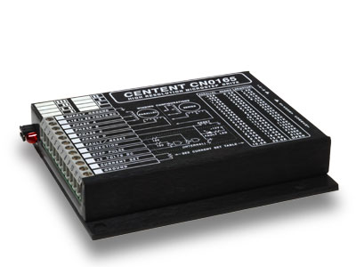
All small-signal diodes in the CN0165 were DO-7 glass hermetically sealed 1N4148s and 1N914As. Problem was the glass to metal seal wasn't quite 'hermetic'. While soaking they absorbed some of this fine elixir and the epoxy encapsulation kept it there for all time.
The stuff began to corrode the diodes and the resulting salts poisoned the silicon and ultimately caused them to fail. Took about 3 months.
We had many hundreds of CN0165s come back failed and it was on my head to answer why. My problem was I couldn't get into the @#%$ drives to see what was wrong; it took weeks to even figure it was the diodes after eliminating everything else.
I hate epoxy encapsulation to this very day.:-)
Sorry for the rambling, long post. Short answer to your question: Designed in the 80s vs. designed in the last few years. Figure on I must have learned something in 20 years.:-)
Mariss
i
-
07-07-2006, 04:31 AM #19
Registered
- Join Date
- Jun 2005
- Posts
- 866
That epoxy by the way is very annoying. I had 3 of these, one blew, and I was wanting to take a peak inside, figuring It's a dead duck anyways. I still want to look inside, Maybe I will use a sawzall
-
07-07-2006, 05:11 AM #20
Gold Member
- Join Date
- Mar 2003
- Posts
- 2839
A hammer and cold-chisel are your tools of choice (they were mine).
1) Place the chisel at the plate/cover intersection on the side of the drive. Give the chisel a really hard smack with the hammer to seperate the two.
2) Use a really stout pair of pliers and an assist from the chisel to seperate the 0.05" cover aluminum from the carcass. Peel the cover off chunk by chunk.
3) This should reveal a faint PCB green along the edge of the black epoxy brick. Do the following very carefully!
4) Place the chisel along the bottom edge of the PCB on the side of the epoxy brick. Line it up very carefully.
5) Give a single, very hard hammer hit on the chisel. Be sure and precise; you are cleaving a diamond.
6) Done really right should result in the epoxy cleanly seperating from the bottom of the PCB. Marvel at the PCB and figure out what's wrong on the top side you cannot get at from the signals you read on the bottom when you power up what's left.
Keep in mind the MOSFETs, some of the bottom ICs and the voltage regulator are gone now; use your creativity to compensate for the now missing parts. Oh, and by the way, figure from what's left what component failed on the other side that resulted in the drive being returned. That's what I had to do.:-)
I really, really HATE epoxy. I won't have in my home.
Mariss

 Reply With Quote
Similar Threads
-
New user, new lathe user, new everything and a daft question
By eddy-r3 in forum Mini LatheReplies: 2Last Post: 06-11-2013, 11:26 PM -
user input
By doug6949 in forum Rhino 3DReplies: 2Last Post: 03-04-2012, 07:25 PM -
New board help requested
By pminmo in forum Open Source Controller BoardsReplies: 32Last Post: 09-30-2008, 11:10 AM -
User input variable - best way?
By markkirby in forum G-Code ProgramingReplies: 6Last Post: 06-02-2008, 03:02 AM -
M109 Interactive User Input
By axis overtravel in forum Haas MillsReplies: 16Last Post: 07-31-2006, 09:55 PM
