


I think using a dedicated encoder buffer is a good idea.Originally Posted by tivoidethuong

Just tell me what u need changed in the code. But why do you need the 100pin mcu? You need more timers or?
Mihai
Results 121 to 140 of 490
-
11-12-2015, 09:46 AM #121
 Registered
- Join Date
- May 2006
- Posts
- 190
Re: DIY BLDC / DC Motor Servo Drive - ARM MCU (STM32F103C8T6)
-
11-12-2015, 10:16 AM #122
Registered
- Join Date
- Nov 2005
- Posts
- 111
Re: DIY BLDC / DC Motor Servo Drive - ARM MCU (STM32F103C8T6)
Hi Punisher454,
please show us your code and schematic.
Hans
-
11-12-2015, 07:33 PM #123
Registered
- Join Date
- Jan 2006
- Posts
- 115
Re: DIY BLDC / DC Motor Servo Drive - ARM MCU (STM32F103C8T6)
I'll have to do some digging to find it. give me a few days. bear in mind the relevant code would only be the commutation table. I doubt it will help much, except to clarify just how simple it can be to do commutation with 3 hall sensors.
-
11-12-2015, 09:23 PM #124
- Join Date
- Sep 2015
- Posts
- 15
Re: DIY BLDC / DC Motor Servo Drive - ARM MCU (STM32F103C8T6)
Hello Mihai and others!
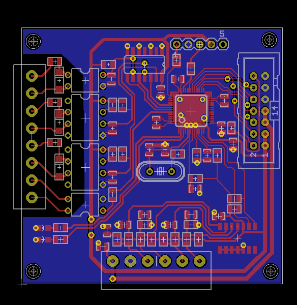
I posted my drive and control board designs to this thread couple of weeks ago. Finally, the PCBs arrived this week and I've now assembled one pair of them. I have tested it only with my own firmware so far, I'll try to test with Mihai's during weekend. Some tweaking of the code will be required as the pin compatibility is not 100%. But with my own fw, everything seems to work fine. Additional features to Mihai's work are HALL sensor support and USART.
There is one design flaw I already noticed before receiving the boards: The 6n137 opto I'm using officially support only 5V supply voltage, but I use 3.3V for it. It seems to work perfectly fine, but still would not recommend using my design without design change.
You can see a photo of the finished driver (still missing USB connector as my code has no support):
https://www.dropbox.com/sc/iwixct5f9...YmRnT9oSvHJ3ca The driver board and the controller board are connected together with standard pin headers + matching length M3 standoff screws, it's not very clear on the picture.
There has been discussion about 26LS32. I'm using it to convert differential encoder signal to single ended before connecting it to my driver and it seems to work very well. It does not require any external components except some supply decoupling caps, so it's very easy to design with. I doubt it needs any software changes if someone wants to add it?
Thanks,
Pekka
-
11-12-2015, 10:54 PM #125
Registered
- Join Date
- Nov 2005
- Posts
- 111
Re: DIY BLDC / DC Motor Servo Drive - ARM MCU (STM32F103C8T6)
Hi Pekka,
will you show us your code too?
Thanks
Hans
-
11-13-2015, 09:56 AM #126
Registered


- Join Date
- Mar 2005
- Posts
- 306
Re: DIY BLDC / DC Motor Servo Drive - ARM MCU (STM32F103C8T6)
finish control stage
-
11-13-2015, 06:46 PM #127
Registered
- Join Date
- Nov 2005
- Posts
- 111
Re: DIY BLDC / DC Motor Servo Drive - ARM MCU (STM32F103C8T6)
Hello,
here is my first test to produce a prototype board with my milling machine, The holes I will drill with handdrilling machine like proxxon.
Unfortunately are there between two copperstripes small pieces of copper not more holding on the epoxiboard an I must them remove manual.
Hans
-
11-14-2015, 11:45 AM #128
Registered
- Join Date
- Nov 2005
- Posts
- 111
Re: DIY BLDC / DC Motor Servo Drive - ARM MCU (STM32F103C8T6)
Hi Mihai,
its possible in a firmware in future to detect the rotorposition in the startsequence with hallsensors? If possible can I use for a new boardlayout the pins B7, B8 and B9? For current limitation I think now its better to shut down the pwm output from the ARM in the firmware, while not every gate drive have a shutdown input .
Thanks
Hans
-
11-14-2015, 05:51 PM #129
- Join Date
- Sep 2015
- Posts
- 15
Re: DIY BLDC / DC Motor Servo Drive - ARM MCU (STM32F103C8T6)
Sure I will. I wrapped my code and the hardware design to a github repo: Originally Posted by Holzwurm56
https://github.com/pekkaroi/bldc-drive
Please forgive me, I'm not at all a software engineer, so I don't think its the best piece of software you've seen, but it is working.
Pekka
-
11-15-2015, 09:20 AM #130
Registered
- Join Date
- Nov 2005
- Posts
- 111
Re: DIY BLDC / DC Motor Servo Drive - ARM MCU (STM32F103C8T6)
Hi Pekka,
I am a software DUMMY , every follower of this thread knows more about software than I. What for a CNC-Controller do you use? All cnc controller uses an output for step, direction and enable from 5Volt or more.
Thanks Hans
-
11-15-2015, 09:26 AM #131
Registered
- Join Date
- Dec 2012
- Posts
- 390
Re: DIY BLDC / DC Motor Servo Drive - ARM MCU (STM32F103C8T6)
No, they don't. I think it is more common for higher-end controllers and drivers to use 0-10V controls instead of step/dir. Originally Posted by Holzwurm56
-
11-15-2015, 09:50 AM #132
- Join Date
- Sep 2015
- Posts
- 15
Re: DIY BLDC / DC Motor Servo Drive - ARM MCU (STM32F103C8T6)
I am using LinuxCNC with step/dir interface with 5V as well. The interface is optoisolated with those 6n137s. The input side logic voltage can be 5v, that is not the problem as optocoupler input is current driven, so you can match the input voltage by selecting suitable resistor. But 6n137 has a logic level output and requires a supply voltage. And as I'm driving the STM32 where all pins are not 5V tolerant, I have to use 3.3V supply for the optocoupler. And that's not allowed even though seems to work just fine. Originally Posted by Holzwurm56
-
11-16-2015, 03:45 AM #133
Registered
- Join Date
- Jan 2006
- Posts
- 115
Re: DIY BLDC / DC Motor Servo Drive - ARM MCU (STM32F103C8T6)
Okay, Originally Posted by Holzwurm56
here is a very simple test program I used to drive a brushless motor that was in an actuator for something I was working on. It had 3 hall sensors built in.
To determine the order in which this thing operated I made a degree wheel and hot glued it to the motor shaft. then I read the hall sensors and turned the shaft by hand and recorded the beginning and ending positions of each sensors on-off states, next I applied power to the motor's coils in all combinations and recorded the shaft position of each combo.
using this data I was able to come up with a commutation table.
The program simply reads the hall sensors and generates a value based on the reading. there are 6 valid states and two invalid states. In testing an invalid state was never detected. The hall sensor state is checked against the table in a select-case method. I am using Infineron BTN79xx or BTS79xx fets which contain a p-channel and N-channel together with some protection logic. Extremely simple, definitely far simpler ,and also about the same final price high side driver schemes.
I had this working with a pot on an ADC channel at one point, but this version is just using a fixed pwm value of 20 which IIRC was a very low speed rotation.
This was written in Bascom and running on a mega168 at 8mhz. I'm sure this could be done much more elegantly in C++ (maybe even stm32duino) on a much faster 32bit ARM.
I no longer have a schematic for this, but it's irrelevant. there were 6 basic outputs, 3 pwm's for the enable lines of the fets, and 3 lines to determine the polarity of the fets.
-
11-16-2015, 04:59 AM #134
Registered
- Join Date
- Oct 2005
- Posts
- 255
Re: DIY BLDC / DC Motor Servo Drive - ARM MCU (STM32F103C8T6)
nice work all!!
Nice to see people that can work together.
Is there any intention to have different control modes? eg possition - speed - torque.
regards to all
Paul
-
11-16-2015, 02:58 PM #135
Registered
- Join Date
- May 2006
- Posts
- 190
Re: DIY BLDC / DC Motor Servo Drive - ARM MCU (STM32F103C8T6)
Congrats on your project Pekka! I've looked in the code and I've seen many improvements. I think you have increased the PID frequency a bit... Originally Posted by roivai
I still think it's a good idea to add USB support. I guess somebody should write a PID tuner program for linux too. Should not be that hard. Lots of computers these days lack a serial port.
Keep up the good work!
Mihai
-
11-17-2015, 04:20 PM #136
- Join Date
- Oct 2015
- Posts
- 44
Re: DIY BLDC / DC Motor Servo Drive - ARM MCU (STM32F103C8T6)
i have not oscillator and i have used osc in my collage but my collage period is over before 2 year ago so i have bought this : Originally Posted by tivoidethuong
HEDL-5640#A13 Avago Technologies | Avago Technologies Incremental Digital Encoder Line Driver, 30000rpm, 4.5 ? 5.5 V | 818-8833 | Welcome to RS Online
i am waiting to arrive stm32 programmer and this encoder i am still waiting because i cant programme the stm32 board without programmer i have bought discovery board instead of stvlink2 because discovery has buitl in stvlink so and little price differnce in my contry ..correct me if i had made some mistake thnks for suggestion
-
11-17-2015, 09:56 PM #137
- Join Date
- Sep 2015
- Posts
- 15
Re: DIY BLDC / DC Motor Servo Drive - ARM MCU (STM32F103C8T6)
Thank you for your kind words Mihai! Originally Posted by mcm_xyz
Yes, adding USB support would be nice, even though I like the simplicity of using USART + USB virtual serial port adapter. You can call me old school there. I will create a tuning SW of some sort sooner or later. So far typing into serial terminal has been sufficient. Also, my primary operation mode will be without PID loop in velocity control mode, where I have the PID loop inside LinuxCNC. And there I have nice tuning capabilities.
I made the PID loop to be driven by a timer. I think I tried to set the PID frequency to about 4kHz (never measured that actually). So I think it's quite bit slower than the frequencies you have been talking about? I like the timer approach as this makes the looptime constant and thus the I and D loop coefficients stable over different loads on the CPU. Also, I don't quite see the meaning of running the PID loop faster than the PWM frequency, so I chose a conservative(?) value of PWM frequency divided by 5.
I've reached speed of 2000 RPM and haven't faced any issues with 4000 ppr encoder, so I think speed will not be an issue. The limiting factor is now my bench power supply voltage. If connected to 48V supply, I'm confident that the rated 3000 RPM could be reached.
Pekka
-
11-17-2015, 11:19 PM #138
Registered
- Join Date
- Nov 2005
- Posts
- 111
Re: DIY BLDC / DC Motor Servo Drive - ARM MCU (STM32F103C8T6)
Hi Mihai,
I get the mini development boards from China. What for a kind of Development System and C-Compiler do you use? Is there a hex-file of your firmware available? Is a executable file of the bootloader and servo drive tuner available?
Thanks
Hans
-
11-18-2015, 10:15 AM #139
Registered
- Join Date
- May 2006
- Posts
- 190
Re: DIY BLDC / DC Motor Servo Drive - ARM MCU (STM32F103C8T6)
I think you were quite right. I was about to move the PID update method to a timer. The idea of it running freely is is to check the best possible speed for executing it and to improve the code. Originally Posted by roivai
Mihai
-
11-18-2015, 10:20 AM #140
Registered
- Join Date
- May 2006
- Posts
- 190
Re: DIY BLDC / DC Motor Servo Drive - ARM MCU (STM32F103C8T6)
Every binary is included. All answers in my previous posts. Please do not ask me how to setup eclipse and stuff... Thanks for understanding. Originally Posted by Holzwurm56
Mihai

 Reply With Quote
Similar Threads
-
servo drive for Fanuc A06b-0116 servo motor, Help
By Cblad in forum FanucReplies: 3Last Post: 02-11-2015, 06:07 AM -
NEED TO KNOW WHICH YASKAWA SERVO DRIVE AND SERVO MOTOR ON EXCITECH E5 HEAVY-DUTY
By M.Abid in forum Excitech routersReplies: 0Last Post: 10-21-2014, 09:29 PM -
Servo Drive AC + servo motor for car steering wheel simulator
By yusukeand in forum Servo Motors / DrivesReplies: 6Last Post: 01-10-2014, 09:06 AM -
VCE-750 with BLDC Servo - X Axis Servo fault
By kostner in forum Haas MillsReplies: 6Last Post: 10-23-2011, 08:09 PM -
Sell Servo Motor, Servo Drive by GSKcnc.com from China
By salecnc@hotmail in forum News AnnouncementsReplies: 0Last Post: 06-03-2008, 08:55 PM
