


Hi,
After a long time, I decided to build the benchtop vertical mill I always wanted. Started the design this week and will appreciate any advice since I will spend many hours on this project and don't want to fail in the end.
The motivation is to have a rigid machine to mill steel that is not too heavy. I decided to go with a steel frame which will be face milled and drilled on a CNC machine as required. I considered welding for the main frame but since I do not have easy access to heat threatment ovens I went with the CNC machined parts to hold the base and the vertical column together. The base and column is ST37 construction steel profile with the dimensions 200x100mm in dimensions and 10mm in thickness. The parts to hold them together will be produced 15mm steel plate. As I mentioned before, the frame will be face milled 0.3mm on a CNC machine from the sides and will be drilled on a CNC referenced to the face that will hold the linear guides.
The guides will be HIWIN HGW 25 CC wide carriage blocks. Also the the ball screws will be RM1605.
The XY table will be made produced in 270mmx900mm with 25mm thickness from steel and T slots surface finish will be produced on a CNC machine as well.
The weigth of the machine is somewhere about 140-160kg right now.
Knowing that the actual loading is not as follows I did some preliminary analysis as below too get a feeling about the machine. Considered 1000N loading applied at location that is assumed to simulate the worst case. I found that cutting load is about 300-800N for the conditions something like 3.5mm cutting depth, 2 flute cutter, 1 inch tool diameter etc.
Vertical column is fixed at the sides as a boundry condition an the 1000N loading applied at a direction that the moment of inertia of the profile is lower. Seem to have 0.15mm deflection at the point that the loading is applied and 0.08 at around the tip. The deflection can be assumed to be around 0.05mm - 0.1mm in the worst case.
The table is also analysed. The deflection at the point that the 1000N load applied will bee small since in reality it will be distributed. However the tip of the table is deflected about 0.17 at the minimum limit due to its own weight. However I thing the machining will always be done in the undeflected portion of the table so it may be is not a big deal.
The deflection of the profile that will hold the spindle (same profile with the base and the column) is also going to have 0.1mm deflection under 1000N loading along the lowest moment of inertia direction. I think about closing the upper and lower sides of the profile to make it more stiff with welding or so...
I also have plan to add a 4th axis and may be a 5th axis in later on and use the machine as a surface and cylindrical grinding machine. Also I may drive the 4th axis with a faster ac motor and use the machine as a lathe by adding a proper fixtures to hold the tools to the spindle holder profile from the sides.
So I will be glad that any body that give advice or answers about the following questions I have.
- Do you think the loading on the machine will go up to 1000N for milling mild steel, 304, 316 and aluminum 7075 for conservative cutting parameters (0.5 depth many passes...)
- Do you think natural frequencies of the machine will be high enough and it will be rigid enough to mill the materials above? Which will be the most problematic, and what would be the limit of such a machine.
- Do you think that I should deal with the table deflection? If so what do you recommend?
- Do you think that the rails and the balls screw will be rigid enough? (They are one of the cost drivers and will be costly to go with the bigger ones.)
Thanks again. Best Regards.
Özgür...
Results 1 to 20 of 29
-
12-29-2015, 11:07 PM #1
 Registered
- Join Date
- Oct 2014
- Posts
- 13
 Vertical Milling/Grinding Machine Build - Advice Appreciated.
-
12-30-2015, 11:53 AM #2
Registered
- Join Date
- Jan 2008
- Posts
- 1538
Re: Vertical Milling/Grinding Machine Build - Advice Appreciated.
Rail size is fine.
Don't design a machine only capable of taking light cuts, you'll hate it in the end.
I think you would be much better with square tubing, e.g. 200x200. It doesn't occupy much more space and is much more rigid.
Build lifting points / holes / hooks in now, so that you can easily and safely move it with an engine crane or similar, or even insert bars for a few people to lift and move it.7xCNC.com - CNC info for the minilathe (7x10, 7x12, 7x14, 7x16)
-
12-30-2015, 09:13 PM #3
Registered
- Join Date
- May 2014
- Posts
- 22
Re: Vertical Milling/Grinding Machine Build - Advice Appreciated.
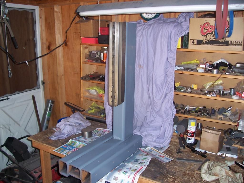
I would encourage you to look at some form of epoxy filler for the steel frame, I built a frame out of heavy steel section for an X2 upgrade and found that while the frame was rigid and allowed heavy cuts, it had very little vibration dampening. Compared to cast iron, steel has poor vibration absorption properties. After filling the frame with epoxy granite the vibration was almost eliminated.
Here's a photo after welding and painting the frame
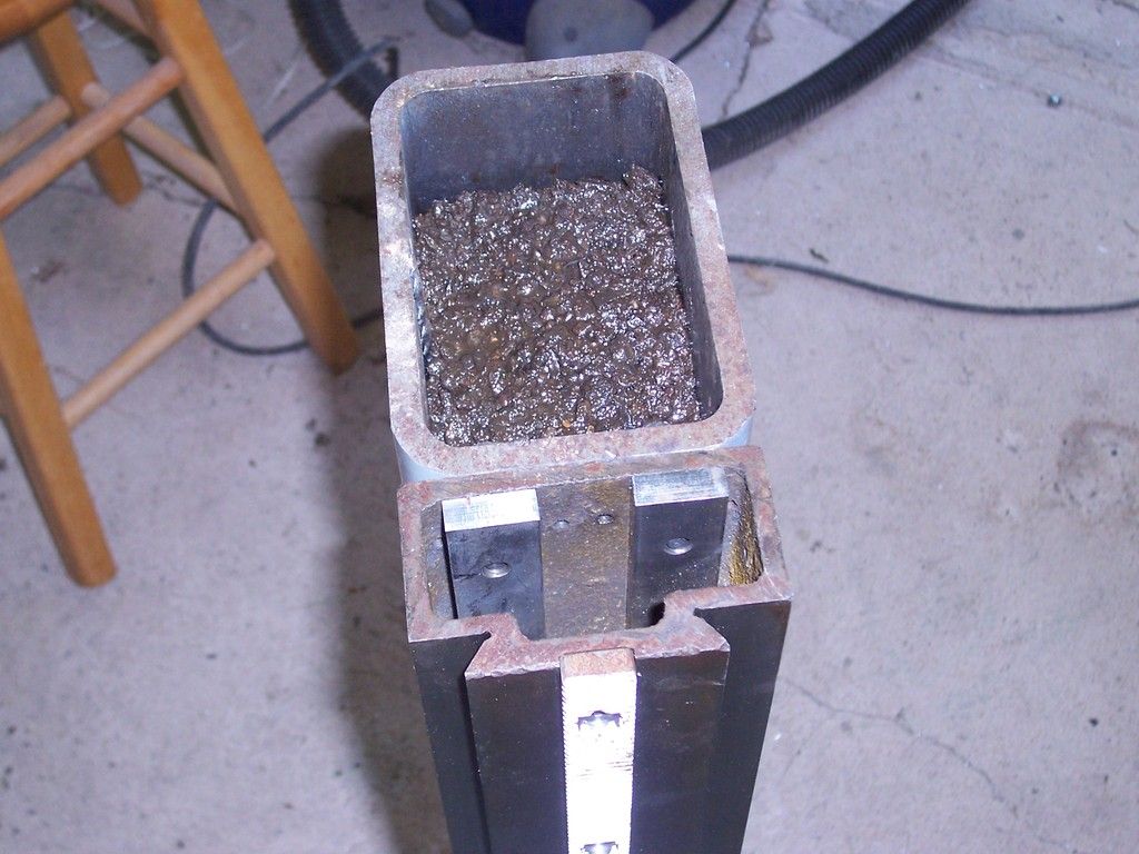
A photo showing the epoxy fill, the base pieces were filled as well.
Regards,
Steve
-
12-31-2015, 06:14 AM #4
Registered
- Join Date
- Oct 2014
- Posts
- 13
Thank you i will consider going with the larger profile and add something to carry the machine. Best regards Originally Posted by pippin88

-
12-31-2015, 06:20 AM #5
Registered
- Join Date
- Oct 2014
- Posts
- 13
Thank you Steve, that was one point I also wondered. I also thought to analyse the natural frequency of the device to see but it is hard to interpret which frequencies is acceptable for the modes. So what you suggested is a very clever thing to do and a must have for me. Best regards. Originally Posted by rythmnbls
-
12-31-2015, 08:54 AM #6
Member
- Join Date
- May 2013
- Posts
- 480
Re: Vertical Milling/Grinding Machine Build - Advice Appreciated.
Bending isn't the primary weakness, but rather the combined rigidity in torsion. when you side load the cutting tool, you are twisting the column, base, headstock/spindle.
-
12-31-2015, 11:23 AM #7
Registered
- Join Date
- Oct 2014
- Posts
- 13
Re: Vertical Milling/Grinding Machine Build - Advice Appreciated.
Considering the suggestions up to now, I worked a bit on the design and need some advice again. I dont have opportunity to lift heavy structures as over 100kg. so it will be carried by me and some friends. The build will be done on the desktop which is at the balcony. So the over all weight should not go over 200kg. And in future if I need to carry it, it will be dismantled to some degree that will be carriable. Saying that, I need to maximize the weight to stiffness ratio.
Right now, I designed the machine base and the column with 200x100x10mm profile. Base is 600mm in length and the column is 1000mm. I digged around in the forum and see that the epoxy granite density is around 2100kg/m3. Calculating the weights of the profile and EG the table below is found.
________Profile_______Profile__EG____Total
Base____200x100x10__25kg___18kg___43kg
Column__200x100x10__42kg___30kg___72kg
Base____200x200x10__35kg___40kg___75kg
Column__200x200x10__57kg___68kg___125kg
By looking at the weights above 200x100x10 profile seems to be the one that I can handle in terms of logistics. For optimising the weight to stiffness ratio and the better vibration dampening characteristics what is the best approach?
1 - Using a 200x200x10 profile as it is and not using EG.
2 - Using a 200x200x5 profile, puting a 100x100x2 profile inside and fill the gap in between with EG.
3 - Using a 200x100x10 profile and fill it with EG.
4 - Design a flat plates of size 200x1000x10 for column and 200x600x10 for base. Make the column and base fully by EG in a mold which will hold the machined plates in place.
5 - Use a different profile such as 200x150 and do something similar to above approaches.
By the way which one would you suggest: st37 steel,st55 steel or iron profiles?
I also have some questions about EG. Is the aquarium granite stones (1mm-6mm particle sizes) suitable for making EG? where did you find the granite stone. Which type of epoxy did you use?
Thanks in advance for the answers.
Best regards.
-
12-31-2015, 03:05 PM #8
Registered
- Join Date
- Jan 2008
- Posts
- 1538
Re: Vertical Milling/Grinding Machine Build - Advice Appreciated.
Rather than use a smaller steel profile inside and filling between, you could use a lightweight material like polustyrene or similar. It would be better to get mass with new epoxy granite rather than more steel that won't contribute that much to stiffness
7xCNC.com - CNC info for the minilathe (7x10, 7x12, 7x14, 7x16)
-
12-31-2015, 03:18 PM #9
Registered
- Join Date
- May 2014
- Posts
- 22
Re: Vertical Milling/Grinding Machine Build - Advice Appreciated.
Here are some more details on my base/column.
Column is 150mm x 100mm x 10mm, height is 900mm
The base is 3 pieces, the two outer parts are 100mm x 75mm x 10mm, length is 600mm. The center part is 100mm x 75mm x 10mm, length is 450mm.
The EG was made from a 40KG bag of "quikrete", the epoxy used was West System 105 resin with 206 hardener. The aggregate to epoxy ratio was 6:1 by volume.
I've estimated the weight when fully assembled with the mill head and table at somewhere between 160 and 180KGs.
The steel used was bought from speedymetals.com, their site lists the material specs as conforming to ASTM-A500.
Regards,
Steve.
-
01-01-2016, 01:44 AM #10
Registered
- Join Date
- Oct 2014
- Posts
- 13
Re: Vertical Milling/Grinding Machine Build - Advice Appreciated.
I thought about the structure today and made some calculations. I decided that the it would be good if I dont exceed 75kg per piece . In that case I can go with one of the follwing if I go with the steel profiles:
1 - 200x100x10mm profile, fully filled with EG (column height 1000mm, column weight 75 kg,profile only area moment of inertia Iy=3.3344e-04 and Iz=1.0784e-04)
2 - 200x150x10mm profile, walls are covered with 40mm EG from inside and the center is filled with Polyurethane Foam (column height 1050mm, column weight 77.5kg, profile only area moment of inertia Iy=4.4184e-04 and Iz=2.7954e-04)
3 - 200x200x8mm profile, walls are covered with 32mm EG from inside and the center is filled with Polyurethane Foam (column height 1100mm, column weight 77.5kg, profile only area moment of inertia Iy=4.5377e-04 and Iz=4.5377e-04)
Stiffness wise by looking at the inertias it seems logical to go with the third option if we do not consider the stiffness added from the EG. Vibration dampening wise I am no sure. Any suggestions?
Best Regards,
Özgür
-
01-01-2016, 06:31 AM #11
Registered
- Join Date
- Jan 2005
- Posts
- 1943
Re: Vertical Milling/Grinding Machine Build - Advice Appreciated.
To drastically increase the torsional stiffness of a rectangular tube you just need to weld caps on the ends.
To help with vibration dampening you can fill with 2-part expanding polyurethane foam. It can be readily purchased in densities from 2 pounds per cubic foot up to about 10 pounds per cubic foot.It won't add much weight but will drastically change the vibration dampening characteristics. This is not the stuff you buy at the hardware store in the aerosol can. It is 2 parts that you mix like epoxy and then pour into place. After a few minutes the chemical reaction will cause it to expand. For a tube , it would only require about a 1 inch hole at one end . Stand the tube up and pour it into the top. The foam will expand and fill the cavity and push its way out of the hole. This is used a lot in marine applications for flotation at the lower densities All welding and machine work should be done and all holes except the fill hole plugged for doing the foam.
As for the design itself, It looks good overall, but the way you have the two rectangular tubes connected will not allow for easy tramming. The way that the RF-45 type machines mount the column would be better in my opinion since you can shim the column base to square the column up to the base..
-
01-01-2016, 11:35 AM #12
Registered
- Join Date
- Oct 2014
- Posts
- 13
Re: Vertical Milling/Grinding Machine Build - Advice Appreciated.
Then 4rth option to the previous list can be added as;
1 - 200x100x10mm profile, fully filled with EG (column height 1000mm, column weight 75 kg,profile only area moment of inertia Iy=3.3344e-04 and Iz=1.0784e-04)
2 - 200x150x10mm profile, walls are covered with 40mm EG from inside and the center is filled with Polyurethane Foam (column height 1050mm, column weight 77.5kg, profile only area moment of inertia Iy=4.4184e-04 and Iz=2.7954e-04)
3 - 200x200x8mm profile, walls are covered with 32mm EG from inside and the center is filled with Polyurethane Foam (column height 1100mm, column weight 77.5kg, profile only area moment of inertia Iy=4.5377e-04 and Iz=4.5377e-04)
4 - 200x200x10mm profile, fully filled with Polyurethane 2 Component ~10lb/ft^3 Foam (column height 1100mm, column profile only weight 65kg, profile only area moment of inertia Iy=5.5024e-04 and Iz=5.5024e-04)
I was also planning to add end caps and even add few end cap like ribs near the middle somewhere that can be weldable for stiffness before the EG fill suggestion. I also agree its a good idea to add end caps in any case. I think the best option may be fourth since I dont know how much stiffness added by EG. If that adds much stiffness than I may consider second or third option as well, any ideas?
I did connect the two tubes together with a plate from the sides thinking that it would be easy to tram the column and the base. Let me explain with pictures.
Both the profiles and the side plate will be machined on a CNC, and I think that if I have problems with perpendicularity, I take out the 1st pin of the column and make fine alignment. But I think since the pins are more than 250mm apart, perpendicularity error should be negligible. That was the concept, instead of welding since welding will deform with time unless heat threaded and machined afterwards. If you still think it would be better to have it any other way i will consider it.
P.S. A few minutes ago I had an idea about reducing the column weight by changing the design a bit. I will increase the length of the base and reduce the length of the column and put the column on top of the base. Hence the base weight will increase and column weight will reduce. So for the weight limit per piece I will modify the options above.
Best Regards,
Özgür.
-
01-01-2016, 04:36 PM #13
Registered
- Join Date
- Jan 2005
- Posts
- 1943
Re: Vertical Milling/Grinding Machine Build - Advice Appreciated.
That will allow trimming forward and backward, but what about side to side?
-
01-01-2016, 04:57 PM #14
Registered
- Join Date
- Oct 2014
- Posts
- 13
Re: Vertical Milling/Grinding Machine Build - Advice Appreciated.
Yes that is correct, it allows in one direction but I was expecting that I would not need any alignment at all since i will have surfaces under the rails face milled and assign the pin locations wrt that datum on both sides. But for some reason if I need any alignment side to side i will be in trouble. So I will consider the suggestion. Thanks.
-
01-01-2016, 08:10 PM #15
Registered
- Join Date
- Oct 2014
- Posts
- 13
Re: Vertical Milling/Grinding Machine Build - Advice Appreciated.
I did make some changes in the design and as I metioned before, shorten the column and put it onto the base considering the weight per part limit. I also worked the connection out, and did connect the profiles together as follows.
First connection style suffers side to side alignment if required later, alignment rely on precision pins machined on CNC, many operations will cost high.
Second connection style, doesnt aligned at first, allows alignment in any direction using shims.
After some more calculation on weight and epoxy price, I decided to go this path. I will use the second connection style. Will get 200x200x10mm profiles weld end caps and connection parts. Paint the profiles and machine the surfaces that has to be precise. Than fill the parts with 2 component 10lb/ft^3 polyuretane foam and integrate the milll. I still need to work the spindle carrying part and the table geometry out and increase the stiffness. Hope I am on the right track I am waiting for any comment.
Best regards
Özgür
-
01-02-2016, 09:34 PM #16
Registered
- Join Date
- Oct 2014
- Posts
- 13
Re: Vertical Milling/Grinding Machine Build - Advice Appreciated.
Hi again, Originally Posted by 109jb
I was searching about the usage of polyurethane foam for vibration dampening, and found some papers about it. But some reported that after some cyclic loading and vibration the foam natural frequency changes. That means the foam loses its property after some time. I know that depends on many parameters however do you have any idea/experience whether that would be a problem? Instead of foam I can proceed with epoxy granite. I also think that since the granite is approximately %85 of the volume that would also add some stiffness to the structure besides vibration dampening but not sure about it. Thanks.
-
01-06-2016, 06:36 AM #17
Registered
- Join Date
- Jan 2005
- Posts
- 1943
Re: Vertical Milling/Grinding Machine Build - Advice Appreciated.
Özgür Originally Posted by ozgur640
Sorry I didn't see this earlier.
I like the new attachment scheme for the column to base better. I however would consider making the blocks that attach to the colum and base for the mate taller in the vertical dimension. Probably twice as tall. It will not add much weight, but will provide less chance for flexing of the joint.
As for the foam. I have extensive experience with the lower density foam used for boat flotation having restored a few boats in the past. The only experience I have for vibration dampening was when I used it in a stand for a drill press that would "ring" at times. I had some of the flotaiion foam left over and used it to fill the legs of the stand. The bottoms of the legs were still open. It did stop the ring, but I van't say anything about the long term as I no longer have that drill press, but it was still fine for the few years I had it after the foam was added. Incidentally, i believe the foam came out denser than the 2 lb/cubic ft it was supposed to because it was old and I'm not sure if it has a shelf life. I hardened up and expanded, but dd not seem to expand like I remembered from when it was fresh when I did my boat. That is just my perception though as I didn't calculate how much to add, I just added enough for it tp come out the end and I cut it off after it hardened.
-
01-06-2016, 02:55 PM #18
Registered
- Join Date
- Aug 2004
- Posts
- 782
Re: Vertical Milling/Grinding Machine Build - Advice Appreciated.
I like the thread !
There are very few machines milling steel .. and there is a reason.
The max end mill your machine can use efficiently, is likely to be about 5-6-8 mm, for steel.
Compare your machine to am original Bridgeport, ie M head.
MT2 socket.
It has similar travels, 800 kg mass, max end mill 1/2" or 12.7 mm, 1/2 Hp was plenty.
Is your machine more rigid than the original bridgeport ?
Technical opinions:
Column is (far) too tall for the section size.
Table is not thick enough.
Base is ok, a bit thicker (50% more) in section would be better.
Technical data:
200x100 vs 200x200 - the latter is 4-8 times better.
Doubling the height of the column needs 8x more mass for equivalent rigidity, and it needs to be 8x more rigid for the same performance.
Example:
My mill is built to mill steel.
At the moment, I am converting to new linear guides (Hiwin 35 mm).
All sides wall thickness is 20 mm in steel (F1 calibrado a basic tool steel in spain).
My section sizes are 240x200 mm on ram: Wall 20 mm.Approx 140 kg.
Spindle mount:
300x240 mm- 530 mm talll: Wall 20 mm. Approx 100 kg.
Verticals (2 of).
250x400 mm- 1300 mm tall. 20 mm front wall, 10 mm side walls.Approx 300 kg. 2 of. => 660 kg total.
Why is the machine so heavy ?
There is a good reason.
All the build is modular, and bolted/tapped.
Biggest pieces are == 140 kg each.
I can move, fairly easily, 140 kg piece alone (2.3 m long).
Lifting one end at a time, with leverage, makes this easy.
Mass is your friend.
Heavier is better.
Nothing is too heavy.
Tiny motors (nema 23 steppers, old setup) will move a 240 kg table, with upto 200 load (capacity over 2 tons, theoretical 10 tons), effortlessly.
My current bridge will be about 700 kg, moving up and down (on 6 linear guides, overconstrained, preloaded).
The small servo motors (nema 23 size, 400 W) are far overpowered (and relatively cheap).
So, my advice is use big sections now, when its cheap.
And, my advice is based on building for milling in steel (my machine is large, thus I need larger section sizes. The ratios stay the same).
I have spent about 12 years at this, mostly full time, so this is my practical experience ...
I expect I might, maybe, be able to use a 20 mm end mill in steel, on the big machine.
(At 3 kW hopefully, with HSM strategies).
Spindle is industrial BT-ISO30, and auto toolchanger.
The larger your work envelope, the more rigid the machine needs to be.
And the mass/rigidity needed is cubed, because its x times y times z.
=> (relates to) section sizes.
A 320 x 240 spindle mount is approx 4x more rigid than 200x200. Its not a linear relationship.
Wall thickness is linear.
20 mm wall vs 10 mm wall => twice as rigid.
Hope this is useful ...
For tests;
Model deflection of 200x200 and 200x100 and look at deflection.
Now try 300x200.
300x200 is likely == 10x more more rigid than 200x100.
For real endmills, you are looking for worst case deflections in 0.02 mm range, or less.
Example:
HGH35-CA
I have theoretical strength of 10 blocks x 4900 kgf each == 49.000 kg.
I expect to get about 300 kgf milling force, or 3000 N (==1-2 kW).
Its possible I might be able to get 1000 kgf, IMO, IME.
I expect, based on lots of experience, to get to use 50:1 load/strength, at best.
This is an example, to illustrate why theoretical calcs are important, and what you should actually expect re: real world.
Using extra rails and blocks makes the system stiffer, averages errors, and makes it more accurate due to geometrical averaging.
Secondary (overconstrained) preload makes it more rigid.
All this for relatively low cost, vs SP / UP blocks and high preload at blocks, at very high cost.
-
01-06-2016, 05:58 PM #19
Registered
- Join Date
- Oct 2014
- Posts
- 13
Re: Vertical Milling/Grinding Machine Build - Advice Appreciated.
First of all thanks to everybody for the suggestions and advice given up to now and guide me to right path. Also thanks for the technical info above. I will consider the details on your message and try to apply them as best as I can. Originally Posted by hanermo
I will use the machine for hobby and making miniature models/engines and parts etc. I have some limitations about my workshop as space and the workshop actually being a 11m^2 balcony. So I need to optimise the design for rigidness, weight and size. I also don't have opportunuty to use a industrial portable winch to carry lift the parts So i limit myself with 75kg per part and trying to get the best out of this limit. I also want to extend the machine to 4th axis.
The design that I come up with your help is below.
Enchancements up to now:
1 - Used 200x200x10mm profiles that will be filled inserterd 100x100x2mm aluminum profile and fill with EG in between. Also fill the aluminum profile with a foam.
2 - Increased the thickness on the connection parts between the column and base.
3 - Added 4 more screws to the sides of the connection parts for lifting the column and easy tramming.
4 - Increased the table thickness to 50 mm but still has plenty of deflection by its own weight as 0.1mm on the tip if the table is on a limit. I have plans to add plates to the sides to increase the stiffness but still not very comfortable, I may decrease the travel for the table and increase the distance between the carrige blocks.
6 - Added some machined surfaces to the sides for alignment purposes.
7 - Added a cap to the spindle holder.
8 - Added lifting points to the CG locations.
Attachment 303026
Attachment 303028
Since I have issues with my belly, I have designed a portable lightweight winch/and carrier table (cannot find a similar product, they were too heavy and big. ) to lift and transport parts from my cars trunk to workbanch at the balcony. Depending on the performance of the lift, I may increase the 75kg per part limit to 100kg per part. In that case I may use a slightly larger profile on the column.
Attachment 303030
I will consider making the following as further.
1 - Shorten the column length as required to go the 200x300x10 or 200x250x10 profile
2 - Shorten the table length and/or consider a table attached to the carrier blocks and rails attached to the part in between the base and the table.
3 - Use a larger profile for the spindle holder part.
I also may have your opinion on the rigidity added to the profile by the EG fill and also changing the way that carry the table as shown below.
Attachment 303032
I actually was going to buy optimum bf20l size machine and try to convert it to CNC but I decided that building the machine as in this thread would be much easier and rigid than that machines. That is the motivation for me and considering the limitations I mentioned I think I can't go further on weight. İ wish I had a garage in that case I would push the limits.
Best Regards
Özgür
-
01-06-2016, 11:34 PM #20
Registered
- Join Date
- Oct 2014
- Posts
- 13
Re: Vertical Milling/Grinding Machine Build - Advice Appreciated.
A few updates:
1 - Increased the table height to 60mm, make T slots according to DIN 508 M12 T Slot Nut with 40mm spacing. Keeping the length same (900mm), lessen the width of the table from 270mm to 190mm. Hope this will eliminate the deflection in a good way. (weight is about 75KG.)
2 - Keeping the base legth same(800mm), Increased the column section size to 250x200x10 (Did not check whether its a standart profile hope it exists, this make the forward travel 50mm less (travel = ~300mm). (Weight is about 85Kg with the EG fill.)
3 - Did not want to limit the z travel so the column length kept the same since I have plans to extend the machine to 4th and 5th axes.
4 - Did not do much on the spinle head since one of the first thing that I plan to do is to produce a heavy duty rotary headstock and vertical rotary table as 4th and 5th axes. Then extend the spindle to a heavy duty ATC one.
Overall weight become about 250Kg which is further away from my first plan
Best Regards
Özgür.

 Reply With Quote

Similar Threads
-
CNC Vertical Double-Surface Grinding Machine
By zhangweilong in forum CNC Machine Related ElectronicsReplies: 0Last Post: 11-26-2014, 07:43 AM -
Hermos CNC Vertical Double-Surface Grinding Machine
By zhangweilong in forum Uncategorised MetalWorking MachinesReplies: 0Last Post: 11-20-2014, 07:29 AM -
sx3 build advice/help appreciated
By kooka in forum X3/SX3/G0619/G0463Replies: 16Last Post: 04-30-2013, 03:00 PM -
advice about tolerances milling/grinding for a student
By veteq in forum Mechanical Calculations/Engineering DesignReplies: 5Last Post: 12-27-2008, 11:53 PM
