


Definitely following this thread and look forward to learn a bit more about how it's all gone together. I hope the aluminum/plastic ways hold up just because I think that's a cool idea I haven't seen executed before. For medium duty it could very well hold up fine? I have no experience with building 3D printers so I think using parts to drive the motors from that community makes total sense from an economy of scale standpoint. Not sure how programming for something like that works to control a 3+ axis machine when 3D printers are typically 3 axis and don't have a spindle ect. You seem to have it all figured out but my experience has been more with conversions using Mach 3 so I am probably missing something simple.
Thread: 7 Axis Swiss Mill-Turn (DIY)
Results 1 to 20 of 142
Hybrid View
-
03-02-2018, 06:39 PM #1
 Registered
- Join Date
- Apr 2012
- Posts
- 32
Re: 7 Axis Swiss Mill-Turn (DIY)
-
03-06-2018, 03:25 AM #2
Registered
- Join Date
- Jun 2014
- Posts
- 25
Re: 7 Axis Swiss Mill-Turn (DIY)
jgwentworth and Hackish,
I've tested several 3d printer boards; Smoothieboard with 5 steppers, Azteeg x3 pro with 8 steppers, and the production version machine will most likely use the Duet board with up to 12 steppers.
3d printer boards also have other inputs and outputs, like lots of thermistors for temperature, heater outputs than can be used for air cylinder and solenoids, display screens, sd cards, lots of limit switches ect.
Embraced and Ianagos,
The spindles on this mill turn center use P5 grade (ABEC 5 equivalent) 15 degree angular contacts with indicators on the outer races.
I picked bearing sizes such that they are also compatible with deep groove bearings and even tapered roller bearings.
This is for forward compatibility, and it gives people the option of replacing bearings cheaply if something bad happens to the originals (at the cost of a couple tenths of runout).
The bearings fit with a very light press fit on the shafts, no play allowed. The housings are blocks of solid 6061 aluminum with close tolerances. This eliminates the slight loss of rigidity from bolting a spindle cartridge into place.
Neither spindle is hardened or ground on the prototype. The big headstock spindle started as a DOM tube with thick walls and a 2 inch bore. There is no need for this thing to be hardened.
The milling spindle started as a solid 2.25" bar of 4140 pre-hard. Since both the taper and the bearing shaft was turned in one chucking, the concentricity of the assembled thing is excellent.
On the production version, the spindles will be made in a CNC lathe with a large collet nose. If the spindles can be turned with tight enough tolerances, grinding won't be needed.
For heat treating, I'm still uncertain. They could be roughed, through hardened, then ground. Or they could be ferritic nitrocarburized for a hard, rustproof skin without warping. Or they could even be PVD/CVD coated.
BTW, the cost of the milling spindle head was about 200 dollars for the prototype. That's for the spindle headstock, spindle tube, P5 bearings, and BLDC motor combined.
Runout at the tool tip is under 0.001", I can't measure any more accurately with the limited tools I have right now. I expect the production machine will range from 0.0002 to 0.0006" at the tool tip .
Onto the "drawbar" and ATC mechanism. The drawbar on the prototype is literally just an M12 socket head cap screw. The bottom of the socket head sits on a roller thrust bearing sandwich.
The production version will have an ultra low friction coating on the threads. With BT30 tool holders, there is no need for pull studs. The drawbar threads directly into the tool holder.
5 foot-pounds on the socket head generates approximately 900 pounds of clamping force between the spindle taper and the tool holder, which is much more than adequate.
There is no risk of the tool holder coming out during milling operations, and no pull stud to fatigue.
The cross section below is a bit outdated, and it doesn't show the mechanism for stopping the drawbar relative to the spindle, but this should give you a general idea of what the inside looks like:
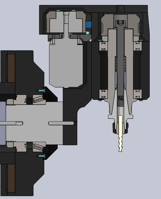
Notice in the cross section photo that there is a spring and stop mechanism around the draw bar. This allows the drawbar to be pushed up by the tool holder before it engages with the threads.
It's kind of hard to explain in words here, but the spindle ATC works by threading and unthreading tool holders into the spindle taper using the milling motor itself.
This is inherently slower than an air cylinder and bellevile stack, but it's ultra compact and cheap in comparison. It also allows for 10 second manual tool changes without power or air.
I know I'm forgetting something that I wrote in my first long response, but it got deleted and I can't remember it now.....
Questions? Comments? Criticism? Let me know!
-
03-06-2018, 04:31 AM #3
Registered
- Join Date
- Feb 2018
- Posts
- 92
Re: 7 Axis Swiss Mill-Turn (DIY)
I think it's very interesting and the machine looks very sexy. I remain unconvinced about the abilities of the machine on anything but the softest of metal. I'm not in any way trying to bust your balls, and I am not a professional machinist nor engineer. I ran a race car fab shop for a number of years, and based on my experience working with different types of metal I have difficulty picturing this thing doing anything that requires rigidity. I would love to see a video taking a reasonable cut with a boring bar on some steel.
-
03-06-2018, 09:20 PM #4
Registered
- Join Date
- Feb 2015
- Posts
- 31
Re: 7 Axis Swiss Mill-Turn (DIY)
I certainly don't want to take away from Generic Default's impressive work here, but...
I absolutely agree with this, and I'm an engineer who's done machine design in a few industries. Originally Posted by hackish

The thing I'd be most concerned about is long term reliability, but the lack of hard numbers on capacity reinforces my suspicion that this isn't going to be taking serious cuts in anything. Saying that the spindle has larger bearings than a Bridgeport is the kind of thing that makes me question the amount of engineering that went into the design in the first place. Larger bearings can't compensate for the overall lack of rigidity in the machine, and aluminum is a poor choice for a small machine where every pound of mass is a plus.
At the right price point (under $5k), I'd probably be willing to try one out once people had trialed it through its teething period. I definitely have aluminum parts that could benefit from the mill-turn setup.

 Reply With Quote
Similar Threads
-
Mill Turn C Axis Programming for OD Pockets BobCAD CAM V28 Mill Turn Standard
By aldepoalo in forum BobCad-CamReplies: 0Last Post: 04-01-2016, 07:55 PM -
Mill Turn 2 Turret Mounting tools BobCAD CAM V28 Mill Turn Standard
By aldepoalo in forum BobCad-CamReplies: 0Last Post: 04-01-2016, 07:52 PM -
Mill/Turn Y axis Instead of C
By FlorinMBV in forum FeatureCAM CAD/CAMReplies: 2Last Post: 03-29-2016, 07:07 AM -
Please advise: Swiss turned plastic parts. Appropriate applicaiton for swiss turn?
By MadMax in forum CNC Swiss Screw MachinesReplies: 15Last Post: 04-14-2011, 05:33 PM -
Swiss turn material
By scook179351 in forum CNC Swiss Screw MachinesReplies: 8Last Post: 05-11-2008, 06:37 AM
