


I found some more time this weekend to progress with making the mechanical components required.
First off I remade the backplate as the hole for the shaft was misaligned by 1mm and I also decreased the clearance between the sliding head and the plate, to increase the mount of material left.
I also made a small 10mm thick spacer plate to fit between the sliding head and the ballnut bracket.
Next job was finishing the design of the ballscrew endplate and the motor mounting plate.
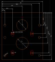
The endplate holds the support bearing for the ballscrew and looks like this in QCAD ...
Attachment 402678
The motor mounting plate will be mounted approx 20mm behind the end plate and the space between contains the drive pulleys and belt, and is attached to the end plate with spacers and M8 bolts. In QCAD it looks like this ...
Thread: Emco F3 mill conversion
Results 1 to 20 of 44
Threaded View
-
09-23-2018, 09:36 AM #13
 Registered
- Join Date
- Mar 2012
- Posts
- 143
Re: Emco F3 mill conversion

 Reply With Quote
Similar Threads
-
EMCO FB-2 CNC Conversion- HELP
By diabolik in forum EMCO MillsReplies: 1Last Post: 07-26-2018, 04:07 PM -
EMCO F1 CNC mill CONVERSION - beginner!
By MrDreee in forum EMCO MillsReplies: 7Last Post: 07-07-2017, 11:03 AM -
EMCO PC 50 Mill Conversion
By blizbiggy in forum EMCO MillsReplies: 4Last Post: 06-11-2012, 06:47 AM -
Emco PC 5 Conversion
By Nigel_B in forum Australia, New Zealand Club HouseReplies: 14Last Post: 10-23-2006, 10:38 AM -
Emco f1 mill conversion help
By no1uno in forum Benchtop MachinesReplies: 5Last Post: 11-10-2004, 09:58 PM
