


Originally Posted by jones

This may be elementary as far as I know but I really like the idea of tacking to your welding table !. All I need is a "real" welding table now....LOL !
Thread: Welded steel frame router build
Results 21 to 40 of 96
-
09-13-2018, 08:47 PM #21
 Registered
- Join Date
- Apr 2010
- Posts
- 17
Re: Welded steel frame router build
-
09-15-2018, 01:49 AM #22
Registered
- Join Date
- Jan 2007
- Posts
- 4
Re: Welded steel frame router build
I worked at a job where they were anal about reducing welding to avoid distortion and save time.
A few suggestions to others from what I learned too many years ago.
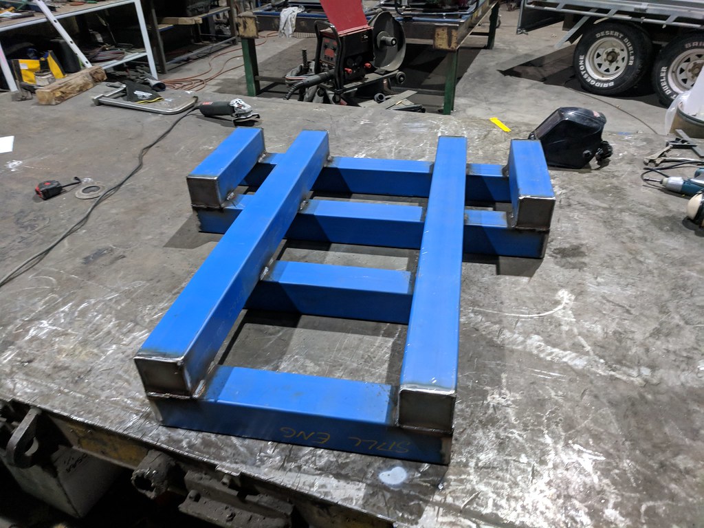
1) On the end caps. Crop the corners of the end caps. On a 100x100 square you can crop 20mm off each end of each corner. Welding in the corner is harder and provides almost no additional stiffness. Now you have welded 240mm of weld versus 400mm. [(100-(2x20)) x 4] That is a 40% saving, with no reduction in strength or stiffness. If you are buying the wire /electrode and the shielding gas that is a big saving in money.
2) On the end caps. Fit them just inside the ends about 8 mm. A fillet weld is about 1/3 to 1/4 the weld volume of an outside corner weld and requires no grinding. It then saves time and grinding wheels as well. Combine this with Item 1 and you will save almost 60% of the welding.
3) On continuous welds. Stitching is good, but with 3mm material, the stitches should be about 30mm max, probably less.
4) On continuous welds, backstep. So a 30mm or shorter weld is made. You move somewhere else and make another 30mm weld. Continue all over the assembly. Now come back to the first and move 30mm away from the previous weld. Then weld back to the previous weld. The previous weld has locked the joint. When you start the back step weld, the parent metal is cold. When you reach the previous weld, the parent metal is getting hot. It cannot distort because it is locked by the previous, now cold, weld.
5) Use chalk and label the weld sequence in advance. So 1, 2, 3, etc. Go diagonally in a symmetrical pattern. Think of the sequence used in torquing down a 6 cylinder engine head.
6) Weld fillet size appears a bit oversize all over. The basic rule of thumb is the fillet size is 1.5mm smaller than the thinner of the 2 materials. Here we have 3mm to 3mm and other sizes to 3mm. So the full strength fillet weld is about 1.5 to 2mm
7) When making any brackets to fit between 2 adjacent pieces, such as 90 degree corner brace, crop the corner at least 20 percent back. You can't weld in there, you don't need to grind off the existing weld, and you save time and reduce the weight of the structure. Strength and stiffness do not change. Time and materials change.
How to determine the approximate backstep length is to observe the back of the material while it is being welded. When it starts to glow red on the back size and clearly show the weld heat, stop. It is when the base material gets red hot that distortion is introduced.
When welding heavy section or thicknesses, like 8 or 10mm stock to 3mm stock, the limiting strength factor is the 3mm material. So the fillet size is determined by that thinner material. It seems counter intuitive to use a 2mm weld when fastening an 8mm plate to the 3mm thick thin material, but it is correct.
Just my thoughts on how to build faster, easier, and cheaper.
What you have done will work very well. It is just that I am lazy and usually pressed for time, so I want all the work savings I can find. Many others are in the same mindset.
Regards
-
09-15-2018, 05:58 AM #23ericks Guest
Re: Welded steel frame router build
Jones....great job!! I love what you doing

-
09-18-2018, 12:16 PM #24
Registered
- Join Date
- Oct 2005
- Posts
- 74
Re: Welded steel frame router build
Wow great info! Some of it I already knew but I'm saving this all for the next time I need to make a welded assembly, cheers! Originally Posted by small_rcer
Thanks man! Originally Posted by ericks
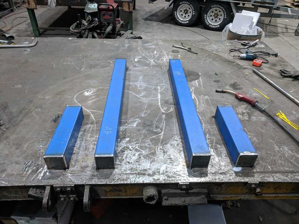
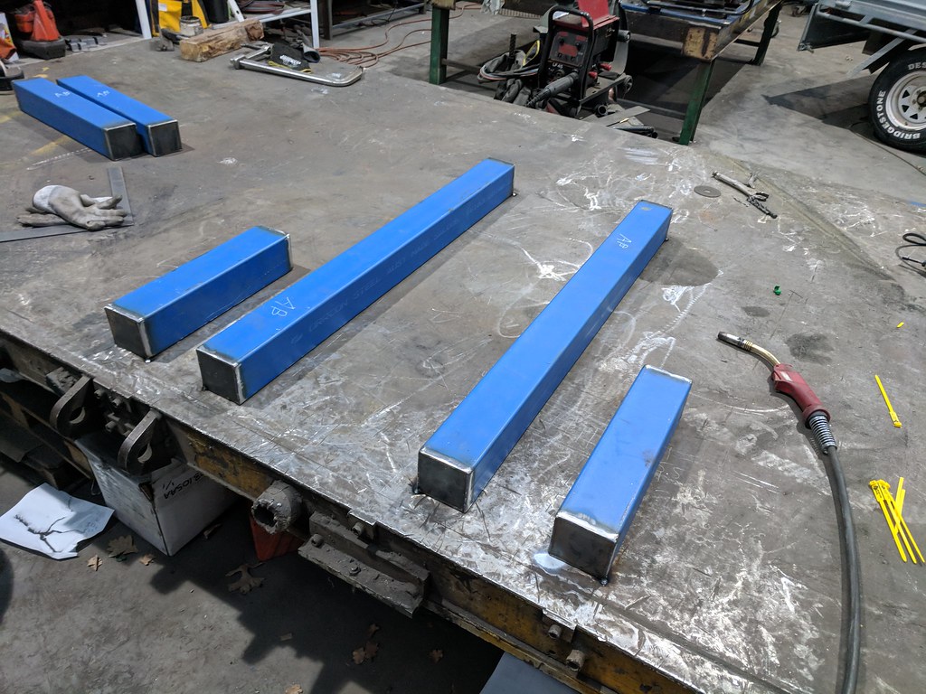
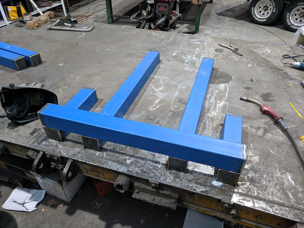
Today I got quite a bit done after work! I welded in some diagonal stiffeners
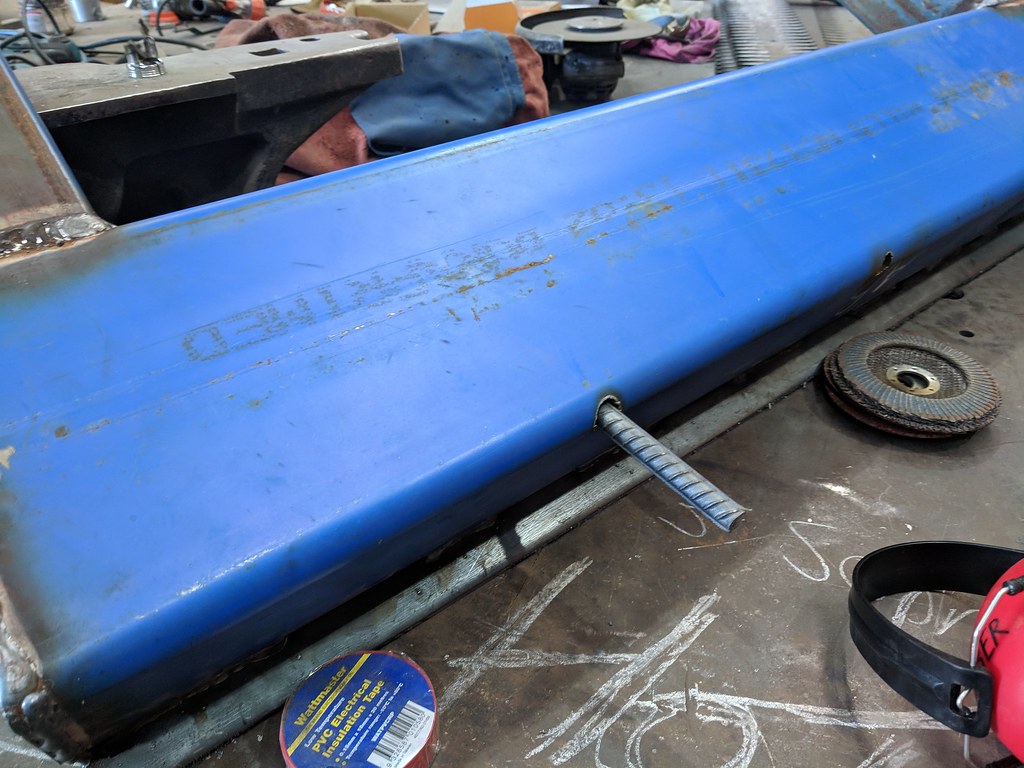
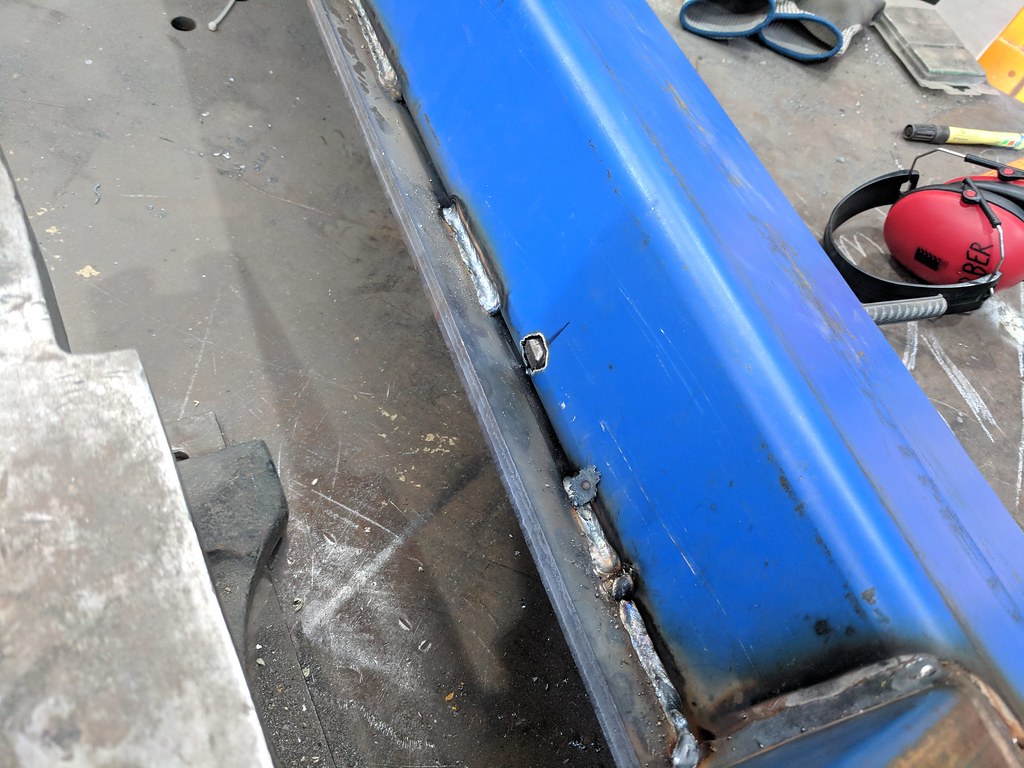
Cut them off, welded them in and then ground the outside smooth.
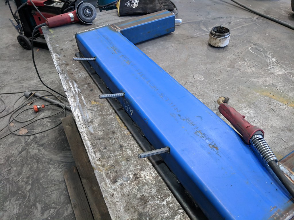
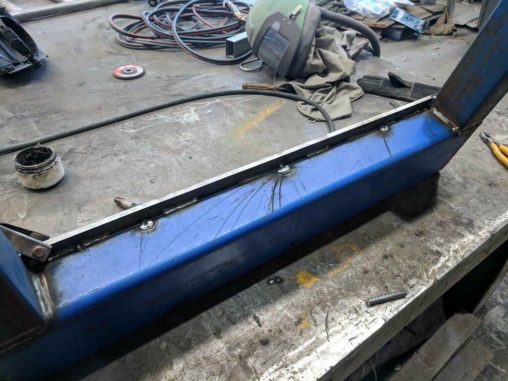
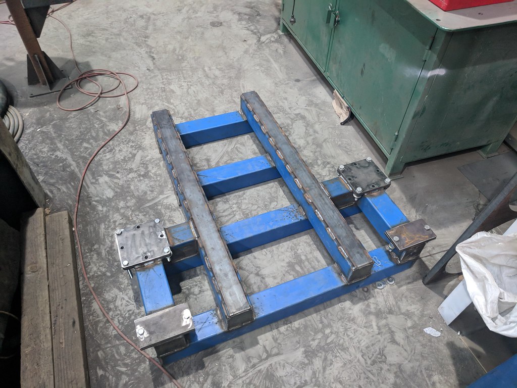
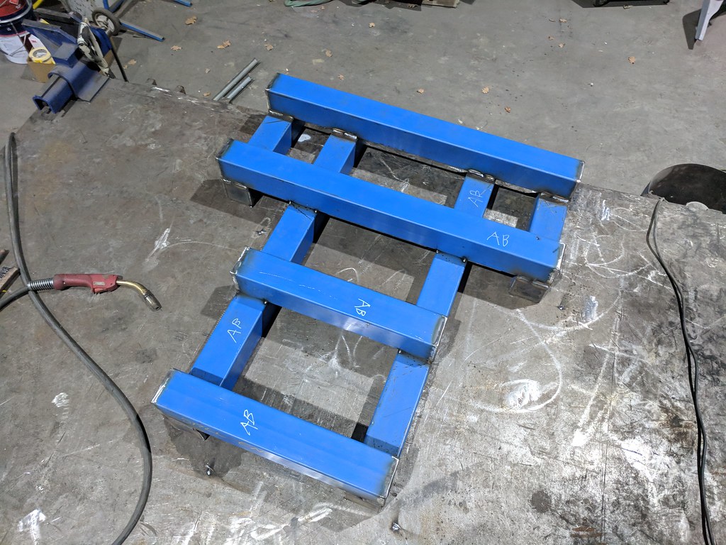
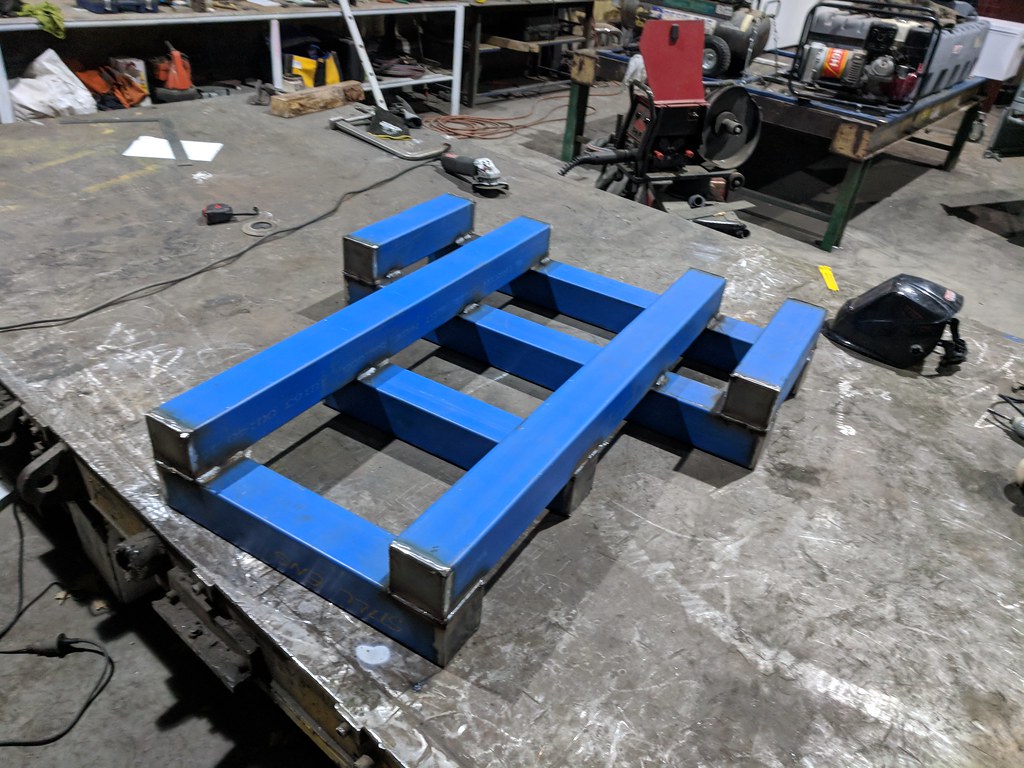
Then I plasma cut out some additional mounting brackets


And welded them onto the base frame
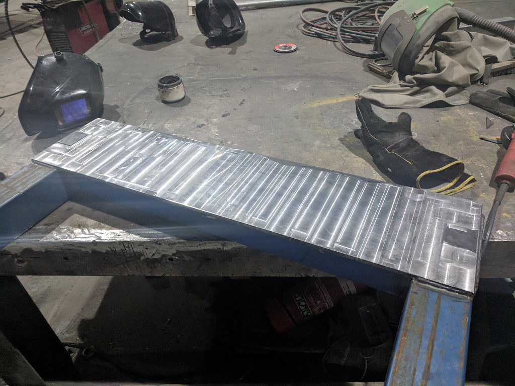
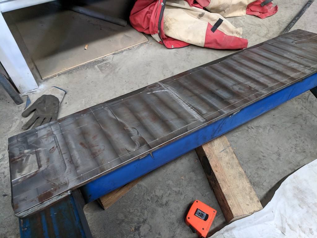
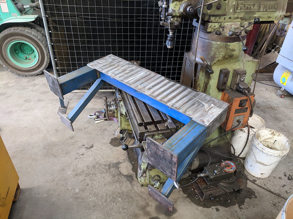
Then I decided to try to machine the mounting face for the rails on the gantry
From this pic you can clearly see how not-flat the surface was
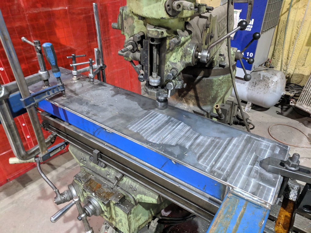


That's getting a bit better

Continued...
-
09-18-2018, 12:17 PM #25
Registered
- Join Date
- Oct 2005
- Posts
- 74
Re: Welded steel frame router build
Mmmmm shiny


The mill is not trammed properly and I didn't have the tools to set it up better. This means the surface is not perfectly even, but it is *fairly* flat. I should be able to lap it to an acceptable tolerance for the profile rails with a straight edge and some emery paper.
-
09-19-2018, 11:09 AM #26
Registered
- Join Date
- Oct 2005
- Posts
- 74
Re: Welded steel frame router build
woops double post
-
09-19-2018, 11:12 AM #27
Registered
- Join Date
- Oct 2005
- Posts
- 74
Re: Welded steel frame router build
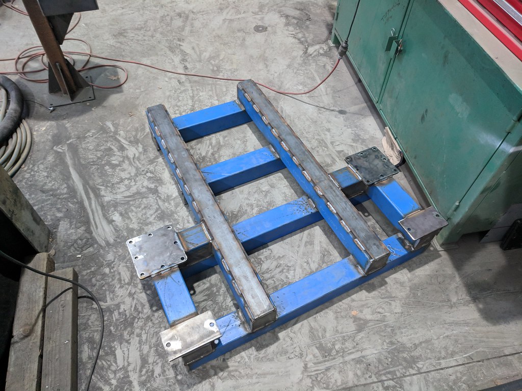
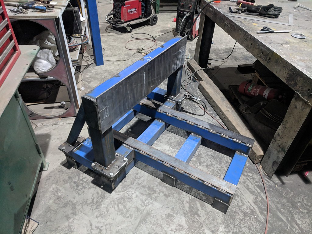
This afternoon I bolted the plates onto the frame
Sat the gantry in position
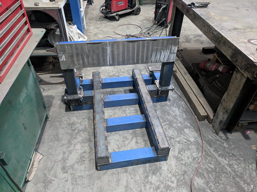
Clamped some RHS perpendicular to the X axis rails

Then once I'd assured myself the gantry was square and in position I tacked it in place and made the rear stays
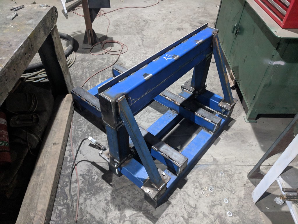
Once fully welded that brings us to this!
I'll need to shim the gantry or Z axis a little bit to make it perfectly perpendicular to the main rails, or maybe the main rails are warped slightly meaning I'll have to get them machined... either way that's a problem for another day!
I'd also like to put some little triangle braces at the front of the gantry legs. I made a slight miscalculation when I placed the footings on the main frame but luckily it won't significantly affect the rigidity of the finished product.
Next up is drilling and tapping the holes for the X and Y axis rails. It won't be long before this actually looks like a CNC machine rather than some weird, abstract scrap metal artwork.
-
09-20-2018, 11:13 AM #28
Registered
- Join Date
- Jan 2008
- Posts
- 1543
Re: Welded steel frame router build
Nice work!
7xCNC.com - CNC info for the minilathe (7x10, 7x12, 7x14, 7x16)
-
09-20-2018, 11:17 AM #29ericks Guest
Re: Welded steel frame router build
You are doing great work mate!!
-
09-20-2018, 12:24 PM #30
Registered
- Join Date
- Mar 2010
- Posts
- 22
Re: Welded steel frame router build
Do you don't do surface Grinding after milling, BTW your design is quiet good but getting such big machine is hard for milling and grinding here. Originally Posted by jones
Please post the rest of the images until you finishes the machine.suresh
-
10-25-2018, 11:33 AM #31
Registered
- Join Date
- Oct 2005
- Posts
- 74
Re: Welded steel frame router build
Thanks, I appreciate the feedback! Originally Posted by pippin88

Thanks mate! Originally Posted by ericks
Well the milling hasn't left the surface very flat; the mill is very old and worn. I'd feel more confident after grinding it, but I'm going to try without just as a test. Originally Posted by endlasuresh
All I've managed to accomplish since the last update is to mark out the holes on the gantry for the mail rails. I have a couple of extra M5 taps and tapping drills arriving soon so next week I'll be putting in all the mounting holes for the gantry linear rails.
I know from building my last CNC (a 5' x 9' plasma cutter) that tapping all these holes in the steel structure is by FAR the most tedious and time consuming part of building the machine. I'm looking at investing in a tapping head to speed up the process.
-
10-25-2018, 04:30 PM #32
Registered
- Join Date
- Dec 2014
- Posts
- 640
Re: Welded steel frame router build
It should survive a nuclear blast!!
-
12-05-2018, 11:48 PM #33
Registered
- Join Date
- Oct 2005
- Posts
- 74
Re: Welded steel frame router build
Haha thanks mate, it is pretty heavy duty! Originally Posted by fretman_2
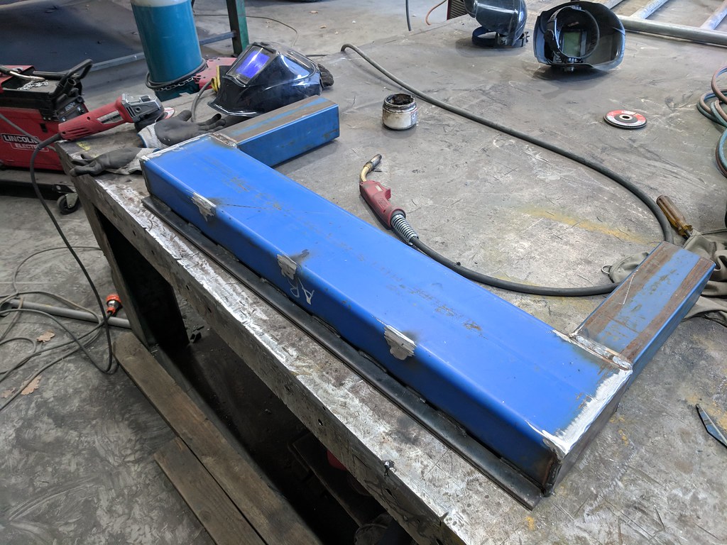
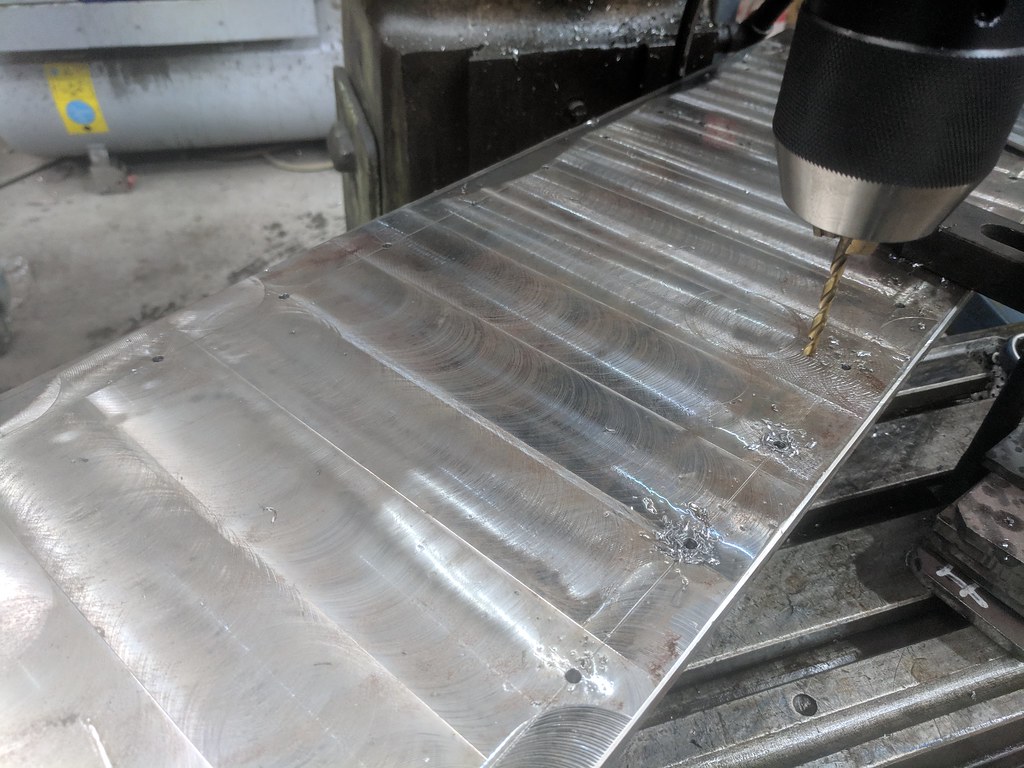
I can't believe it's been so long since I updated this thread but I've been making excuses to put off drilling and tapping all the holes in the gantry. It's way too heavy to lift comfortably and I've been wondering how I'm going to drill all the holes.
 IMG_20181205_163003 by jones_fli, on Flickr
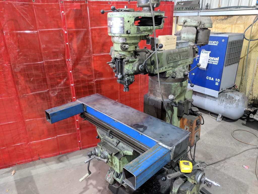
We recently bought a drill chuck for our mill which gave me a perfect way of doing it.
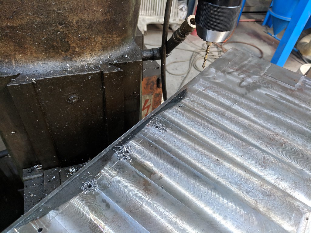 IMG_20181205_172047 by jones_fli, on Flickr
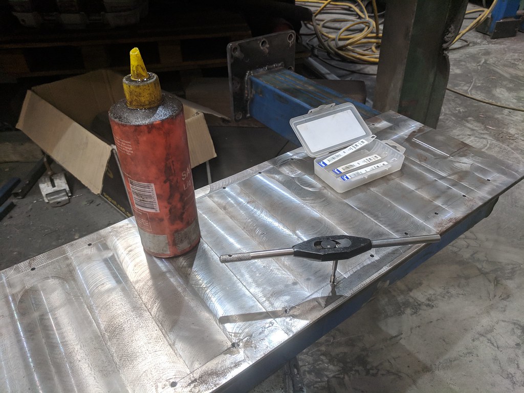
 IMG_20181205_180522 by jones_fli, on Flickr
I'll be tapping all those holes tonight; In the mean time the CAD model has progressed to a point where all the important details have been nutted out and have dimensions, so next week I'll make a start on the X and Z axis pieces.
-
12-06-2018, 08:33 PM #34
Registered
- Join Date
- Apr 2010
- Posts
- 17
 Re: Welded steel frame router build
small_rcer good, detailed information. Thanks for taking the time to share this info..... Originally Posted by small_rcer
Re: Welded steel frame router build
small_rcer good, detailed information. Thanks for taking the time to share this info..... Originally Posted by small_rcer
-
12-06-2018, 09:53 PM #35
Gold Member
- Join Date
- May 2005
- Posts
- 3920
Re: Welded steel frame router build
Some nice work on the gantry. You highlight a common problem with working with steel - it gets heavier everytime you weld something to it. ??????. I strained by back recently working on a press weld up so all I can say is be careful! Get help either human or mechanical when needed otherwise your build will get delayed by weeks as you recover.
By the way it is likely too late but you only really need to machine the gantry where stuff is mounted. On a wide beam like that it would have saved a lot of work. I like the way you welder in the stiffeners though. It is always good to see yet another way of doing it.
Edit:
It just occurred to me, with all of that powder blue paint on the steel you could call it the first Smurf CNC.
-
12-11-2018, 09:52 PM #36
Registered
- Join Date
- Oct 2005
- Posts
- 74
Re: Welded steel frame router build
Haha thanks wizard, I am always careful when moving the thing. Luckily as soon as I drill and tap the holes on the base for the rails that *should* be every operation that I need to actually take the machine over to the tool. Originally Posted by wizard
You're absolutely right with regards to machining the gantry, but I also need a bit in the middle machined down to provide clearance for the ballnut mount, so I figured I'd do the whole thing.
Smurf CNC... I LIKE IT!
Another small update, got all 34 holes on the gantry tapped M5x0.8.
What a painful process! Now to do it all again for the Y axis...
-
07-14-2020, 11:59 PM #37
Registered
- Join Date
- Oct 2005
- Posts
- 74
Re: Welded steel frame router build
Thread resurrection!
After moving from Bathurst back to Sydney and spending a year at an apartment with no real garage to work in, I'm now almost in a position to finish off (haha) my CNC router project.

Not ideal, but there is a lot more room behind me that's not visible in the pic.
Progress so far is I've drilled and tapped the main structure for the long axis rails and I've bought new profile rails for the gantry and z axis. I'm still keeping the round rails on the long/table axis as I can't get the base ground flat anywhere, and frankly I just want the machine up and running !
Next step is to make the Z axis as a separate module and go from there.
-
07-27-2020, 12:47 PM #38
Registered
- Join Date
- Oct 2005
- Posts
- 74
Re: Welded steel frame router build
Since I don't really have access to my mill-drill I've been trying to make do with this ancient drill press I've got.


With all screws tightened down it doesn't bind at all! Very excited, next up is the Z axis plate.
-
08-03-2020, 12:04 AM #39
Registered
- Join Date
- Oct 2005
- Posts
- 74
Re: Welded steel frame router build
Ancient drill press strikes again - the Z axis plate now has rails!

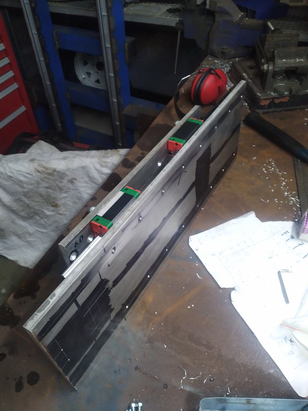
Next up is some 20mm thick spacer blocks for the linear rail carriages to make more room for the ballscrews, then ballscrew and stepper mounts on the Z axis, then Y axis ballscrew mounts, side-plates to reinforce the whole Z-axis assembly, spindle mount, X-axis table, X-axis ballscrew mounts and... that's the bulk of the motion control stuff out of the way :P
-
08-03-2020, 03:03 AM #40
Member
- Join Date
- Jul 2018
- Posts
- 6534
Re: Welded steel frame router build
Hi Jones - Great to see this on the move again. Peter

 Reply With Quote
Similar Threads
-
Steel Frame Router Build
By trailerparkboys in forum CNC Wood Router Project LogReplies: 1Last Post: 03-08-2016, 01:53 PM -
Steel frame Ganrty router build
By matth in forum CNC Wood Router Project LogReplies: 172Last Post: 10-30-2014, 08:32 PM -
My First All Welded Steel Router Design
By widgitmaster in forum CNC Wood Router Project LogReplies: 9Last Post: 10-18-2008, 03:07 PM
