


You need to explain EXACTLY what you want to do. I think that FA/FB is a relay output? There's a parameter to set it to one of ±20 functions.
Thread: New UC300ETH breakout board.
Results 161 to 180 of 183
-
02-23-2019, 07:20 PM #161
 Community Moderator
- Join Date
- Mar 2003
- Posts
- 35538
Re: New UC300ETH breakout board.
Gerry
UCCNC 2017 Screenset
http://www.thecncwoodworker.com/2017.html
Mach3 2010 Screenset
http://www.thecncwoodworker.com/2010.html
JointCAM - CNC Dovetails & Box Joints
http://www.g-forcecnc.com/jointcam.html
(Note: The opinions expressed in this post are my own and are not necessarily those of CNCzone and its management)
-
02-26-2019, 07:16 PM #162
Registered
- Join Date
- Oct 2016
- Posts
- 66
Re: New UC300ETH breakout board.
I wired my UB1 similarly as shown in the diagram attached. When the eStop is pressed, the relay is de-energized and cuts 24v power to the Nema drivers and also cuts the x103 circuit which triggers the software estop. Originally Posted by ger21

I do not know how to use the same estop to turn off the vfd. I only mentioned FA & FB from an older post where someone used it for estop but did not specified how.
-
04-19-2019, 01:27 AM #163
Registered
- Join Date
- Jul 2017
- Posts
- 2
Re: New UC300ETH breakout board.
Seeking recommendations on how and where to connect a simple E-Stop N.C. switch on the ETH300-UB1 without using a contactor or relay
Thanks
-
04-19-2019, 01:36 AM #164
Community Moderator
- Join Date
- Mar 2003
- Posts
- 35538
Re: New UC300ETH breakout board.
X103-X115(any one) to 0V.
Gerry
UCCNC 2017 Screenset
http://www.thecncwoodworker.com/2017.html
Mach3 2010 Screenset
http://www.thecncwoodworker.com/2010.html
JointCAM - CNC Dovetails & Box Joints
http://www.g-forcecnc.com/jointcam.html
(Note: The opinions expressed in this post are my own and are not necessarily those of CNCzone and its management)
-
04-19-2019, 01:41 AM #165
Registered
- Join Date
- Jul 2017
- Posts
- 2
Re: New UC300ETH breakout board.
Thanks I did that and also selected pin3 on port 1... went low and high....no success...I'll double check continuity through out
-
04-19-2019, 01:47 AM #166
Registered
- Join Date
- Nov 2006
- Posts
- 61
Re: New UC300ETH breakout board.
Originally Posted by Rybat57
You can connect N.C switch across X103 and 0V.
In the software configuration, setting the Estop signal to i102 ( port1, pin2).
Later on, you can add any fault signal (Normally Close contact) to X104-110 and activate safety function for each input by soldering solder jumper at the bottom of the UB1 board.
On the diagnostics page of UCCNC, you can see LED status while you toggling the switch. Originally Posted by Rybat57
Weerasak.
www.CNCRoom.com
-
02-09-2020, 04:02 AM #167
Registered
- Join Date
- Aug 2016
- Posts
- 37
Re: New UC300ETH breakout board.
Hello. Recently purchased the UB1 and long time UC300ETH/UCCNC user. I can't seem to find out any info on the switching frequency of the isolated inputs on the UB1 and don't see any non-isolated inputs? Would it be better to use one of the port outputs and use non-isolated input board for an encoder inputs? My encoder input is for the spindle, which can run up to 10k RPM, so worried about saturation of the input opto-couplers on the isolated inputs. So trying to determine if I should just get an add-on board to begin with for the spindle encoder input.
Thanks for any information.
-
02-09-2020, 04:29 PM #168
Community Moderator
- Join Date
- Mar 2003
- Posts
- 35538
Re: New UC300ETH breakout board.
Email CNC Room, he's very helpful.
Gerry
UCCNC 2017 Screenset
http://www.thecncwoodworker.com/2017.html
Mach3 2010 Screenset
http://www.thecncwoodworker.com/2010.html
JointCAM - CNC Dovetails & Box Joints
http://www.g-forcecnc.com/jointcam.html
(Note: The opinions expressed in this post are my own and are not necessarily those of CNCzone and its management)
-
02-09-2020, 06:09 PM #169
Registered
- Join Date
- Aug 2016
- Posts
- 37
Re: New UC300ETH breakout board.
Thanks Gerry. I didn't know contacting CNC room would go to the person making the UB1. Message sent. Will post back here any info just in case someone else is interested. Originally Posted by ger21
-
02-09-2020, 07:58 PM #170
Community Moderator
- Join Date
- Mar 2003
- Posts
- 35538
Re: New UC300ETH breakout board.
Yes, Weerasak makes the boards and answers all the emails.
Gerry
UCCNC 2017 Screenset
http://www.thecncwoodworker.com/2017.html
Mach3 2010 Screenset
http://www.thecncwoodworker.com/2010.html
JointCAM - CNC Dovetails & Box Joints
http://www.g-forcecnc.com/jointcam.html
(Note: The opinions expressed in this post are my own and are not necessarily those of CNCzone and its management)
-
02-10-2020, 02:13 PM #171
Registered
- Join Date
- Nov 2006
- Posts
- 61
Re: New UC300ETH breakout board.
I used to measure some inputs waveform of UB1 and posted in CNCdrive forum.
forum.cncdrive.com • View topic - adjustable debounce settings - suggestion
The falling time is 7.6 micro second. However, fully one pulse will consist of falling time + settle time + rising time + settle time. From the above information, I wound probably multiple by 10 times for the worst case. Then, I simply convert to RPM by using an online calculator. the final result is 789,473 rpm.
https://www.sensorsone.com/period-to...cy-calculator/
On the similar input circuit of MB3, the software Mach4 able to read index input up to 862,200 rpm.
However, In a few days I will check from the real UB1 and UCCNC again.Weerasak.
www.CNCRoom.com
-
02-10-2020, 02:49 PM #172
Registered
- Join Date
- Aug 2016
- Posts
- 37
Thanks, but forgot to mention I'm using a quadrature encoder for spindle PID and rigid tapping. So the PPR will be much higher on the A/B channels. Currently the C11G board I'm using has 4MHz opto-isolators which allows me to use 200 PPR (set in UCCNC at 400 as it reads rising and falling edges) and I can still register 10k RPM. Any higher and it saturates the board. Originally Posted by vrasak
I thought you may have an actual frequency spec for the opto-isolator chips you used on the UB1 board so I could calculate out my max PPR. I'm using CUI AMT-102V encoders with adjustable resolution.
Based on your calculated example above, it looks like you have roughly 13.3KHZ opto-isolators which will be too slow for me to use for the PID feedback in UCCNC.
-
02-11-2020, 05:07 PM #173
Registered
- Join Date
- Nov 2006
- Posts
- 61
Re: New UC300ETH breakout board.
Hi,
Today I had a chance to hook things up and made a measurement waveform right on UC300 pins. The bad news is that the original UB1 V1.6 will catch endcoder signal at the maximum at 4.95khz due to conservative pull up resisters on certain pins. The picture below shows distortion of waveform.
Weerasak.
www.CNCRoom.com
-
02-11-2020, 05:22 PM #174
Registered
- Join Date
- Nov 2006
- Posts
- 61
Re: New UC300ETH breakout board.
Continue from the previous post.
After changing the pull-up resistor from 4.7K to 1K. the waveform looks much better. However, this modification can achieve target only 13.66 Khz
The below waveform is still in good shape. However, if we increase frequency higher than this, the position count is not correct. I haven't had a chance to check the maximum frequency that UC300ETH able to catch.
The locations of the pull-up resistors need to be changed.
Weerasak.
www.CNCRoom.com
-
02-12-2020, 10:13 AM #175
Registered
- Join Date
- Nov 2006
- Posts
- 61
Re: New UC300ETH breakout board.
Since all hardware are already on the work bench. So, I take a chance to measure UC300ETH encoder input. This time I wire up quadrature signal from the ESS/MB3 to UC300ETH directly. This way UC300ETH gets proper waveform.
From this experiment shows that UC300ETH able to catch quadrature encoder frequency at about 20 khz. The encoder position is starting inaccurate if go beyond than this.
Weerasak.
www.CNCRoom.com
-
02-12-2020, 10:43 PM #176
Registered
- Join Date
- Aug 2016
- Posts
- 37
Re: New UC300ETH breakout board.
Thanks VRASAK, I appreciate the information. For some reason, I never got any notification of this last reply, but just decided to check today.
Anyway, based on your very first post, it was apparent the UB1 isn't designed for a quadrature encoder. To me, this would be a good addition to the board since UCCNC requires a quadrature for PID spindle control and rigid tapping. You would just need 2 high speed inputs (or just straight logic inputs with no isolation) for the A/B channels. But I guess for now, I'll just have to break out one of the pin headers for my encoder. Shouldn't be that big of a deal.
Thanks for the information. Now I just need to get this UB1 incorporated into my new control system with all the new DMM servos and servo spindle drive.
-
02-12-2020, 10:52 PM #177
Registered
- Join Date
- Aug 2016
- Posts
- 37
Re: New UC300ETH breakout board.
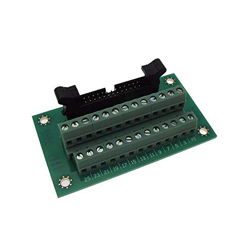
So I'm thinking about just using this to breakout the port 4 or 5 IDC header for my encoder. You think it should be OK for this purpose?
-
02-13-2020, 07:38 AM #178
Registered
- Join Date
- Nov 2006
- Posts
- 61
Re: New UC300ETH breakout board.
You can connect the AMT encoder signal directly to the LPT4 and LPT5 as shown in the schematic below. This connection, the encoder will be part of the controller circuit. So, shield cable may be needed and it must be connected to the motor frame because we don't want to bring the picked up noise back to controller.
Weerasak.
www.CNCRoom.com
-
02-13-2020, 08:43 AM #179
Registered
- Join Date
- Aug 2016
- Posts
- 37
Re: New UC300ETH breakout board.
Thanks. Will do the shielded wire for sure. But for a few bucks, it's nice to have terminals to connect and I have plenty IDC26 cable laying around. LOL, i knew keeping those old computer stuff would come in handy one day.
-
02-20-2020, 09:22 PM #180
Registered
- Join Date
- Aug 2016
- Posts
- 37
Re: New UC300ETH breakout board.
So I haven't had a chance to test this out yet (as I'm still getting my new electrical enclosure together, but what frequency can the pass through ports handle (ports 4 or 5)?

 Reply With Quote
Similar Threads
-
ES-DH2306 Drive with UC300ETH Motion Control Board
By Andrew22 in forum LeadshineReplies: 25Last Post: 12-13-2016, 08:44 PM -
Help deciding which breakout board or driver board etc to use!
By localbroadcast in forum Servo Motors / DrivesReplies: 7Last Post: 06-09-2016, 09:25 PM -
BREAKOUT BOARD INTERFACE BUFFER BOARD
By deslee in forum Servo Motors / DrivesReplies: 1Last Post: 08-17-2014, 07:32 PM -
Breakout Board!!!???
By Knucks in forum Stepper Motors / DrivesReplies: 2Last Post: 03-25-2013, 10:12 AM -
Breakout board, Relays on board?
By Cooper in forum Open Source Controller BoardsReplies: 11Last Post: 06-10-2007, 01:55 AM
