


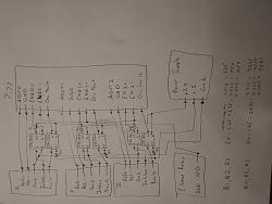
Sure, here are some pics of the wiring diagrams and the board I made to do the interfacing. The analog pairs don't go through the board but rather are direct connected. The EStop connection shown is to my EStop relay which for this item is wired normally open (E-Stop tripped) to digital ground. R1, R2, and R3 should be 200 - 1K ohms and R4, R5, and R6 should be 1K - 6K ohms. I used 1K for all 6. Ideally R4, R5, and R6 would be closer to 5K to reduce the current draw. Let me know if you have any other questions on this.Originally Posted by CATCH22

Attachment 421156
Attachment 421158
Results 1 to 20 of 27
Threaded View
-
05-30-2019, 05:46 AM #11
 Registered
- Join Date
- Apr 2005
- Posts
- 72
Re: Setting up AMC BE25A20 in torque mode?

 Reply With Quote
Similar Threads
-
What is - Torque Mode? Position Mode? Speed/Velocity Mode?
By sunmix in forum Servo Motors / DrivesReplies: 48Last Post: 01-20-2024, 10:34 AM -
Speed vs. Torque mode
By arvidj in forum Dynomotion/Kflop/KanalogReplies: 5Last Post: 06-17-2013, 03:55 AM -
Step Response graph in Torque Mode
By Dr.Nos in forum CNC Machine Related ElectronicsReplies: 2Last Post: 10-27-2012, 09:57 PM -
Torque Mode vs Velocity
By K&T EB in forum CamSoft ProductsReplies: 4Last Post: 01-06-2010, 03:40 PM -
AMC BE25A20 drive in encoder velocity mode.
By lucas in forum Servo Motors / DrivesReplies: 0Last Post: 04-02-2009, 06:58 PM
