


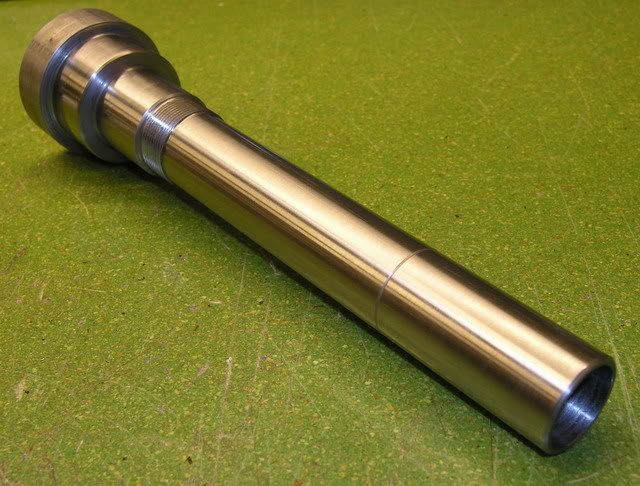
Next task to tackle was making the actual spindleshaft. It's made of steel (2511) and the lower end will be hardened and ground. Here's a photo of how it looked after the first operation:
The threads are M32 X 1,5 and will be used to press the inner rings of the two lower bearing together. The outer rings will be pressed together by the lower flange. What's left to do here is an internal thread at the top that will be used to hold the drawbar assembly in place as well as preloading the spring washers. And to machine it to length and turn the taper for the toolholder.
Turning the taper wasn't as easy as I thought it would be, (never done it before) it took two testpieces and a lot of fine adjusting the cross-slide to get it good enough.
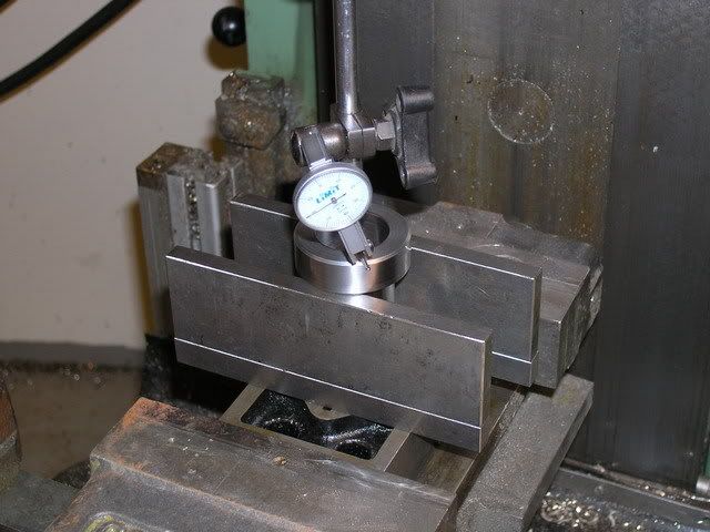
Here's a photo of the setup I did when milling the slots for the drivdogs. I made a "collet" to hold the shaft while maching the taper and used it in this setup as well to clamp the shaft between two vee-blocks.
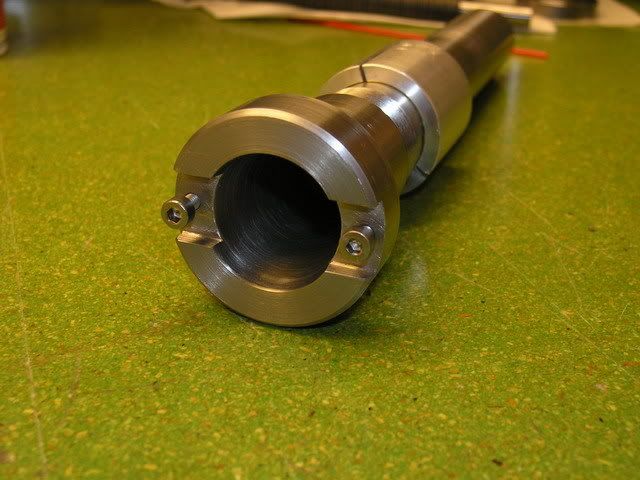
And here's the finished spindleshaft. You can see the "collet" just above the threaded section.
The spindle shaft and the drawbar assembly have now been sent out for hardening and grinding. Hopefully I'll have it back in a week or two.
Thanks!
/H.O
Thread: BT30 Spindle project
Results 1 to 20 of 174
Threaded View
-
07-28-2007, 08:14 PM #5
 Registered
- Join Date
- Jul 2007
- Posts
- 887

 Reply With Quote
Similar Threads
-
BT30 Spindle cartridge for a smithy mill
By mlennon in forum Maintenance DIY DiscussionReplies: 0Last Post: 03-12-2013, 05:13 PM -
Looking for a BT30 Spindle
By xtwalt in forum Uncategorised MetalWorking MachinesReplies: 1Last Post: 11-20-2012, 10:10 PM -
BT30 Spindle
By dirtridn2010 in forum Tormach Personal CNC MillReplies: 0Last Post: 05-07-2012, 11:19 AM -
Reasonably priced BT30 ATC spindle.
By dwalsh62 in forum News AnnouncementsReplies: 0Last Post: 05-12-2011, 05:59 PM -
BT30 taper spindle for mold making
By grantmi1 in forum Hard / High Speed MachiningReplies: 5Last Post: 02-28-2006, 09:41 AM
