


I'm picturing something horizontal all of the sudden! I'll keep you guys updated.
Results 21 to 40 of 43
-
09-11-2007, 03:20 PM #21
 Member
- Join Date
- Feb 2007
- Posts
- 133
-
09-11-2007, 04:33 PM #22
Registered
- Join Date
- Mar 2005
- Posts
- 1136
if you go horizontal then the z axis is 24" and has the weight of the table and work included

maybe do an analysis of intend use - are you ever going to need 16" of Z travel in a machining operation? yes a full size mill has that much daylight or more, but this is to accommodate set ups and tooling - stuff that is more or less static when machining starts.
a traditional vertical mill gives you two Z axis movements, knee and quill. what if you borrowed this page and did the same? some slow bulky way (hydraulics with a linear encoder & dovetails?) to fix the set up and then a small, say 4-6" of movement, Z axis to do the operation. the first would give the big range of motion, and would get locked when set up was completed. then the shorter Z axis would take it from there for the actual machining.
starting to sound like a bport conversion though
-
09-11-2007, 07:27 PM #23
Member
- Join Date
- Feb 2007
- Posts
- 133
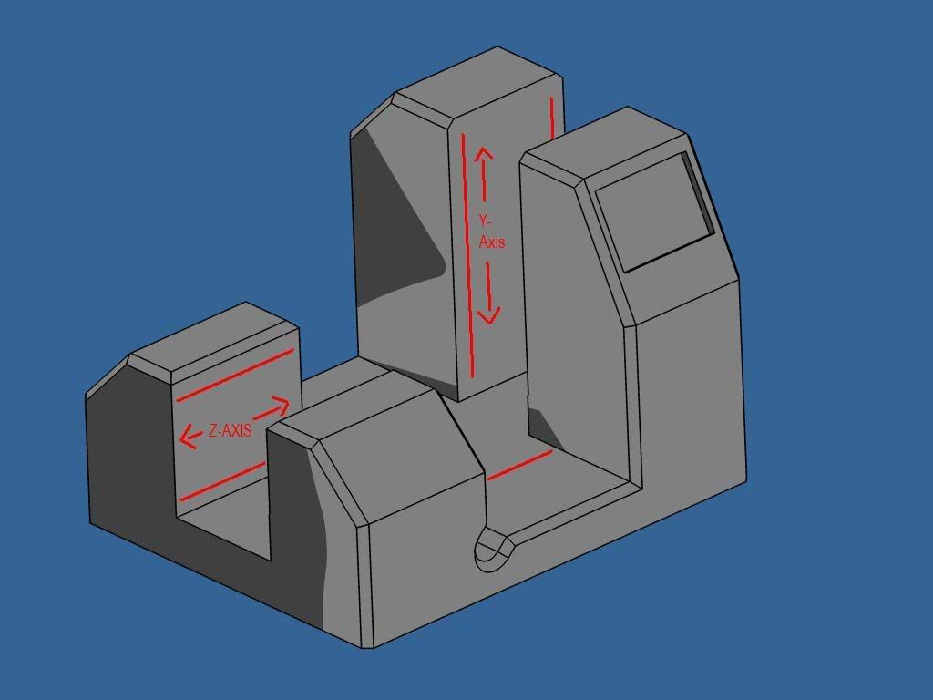
okay, so here's a start on a horizontal. This seems to me to be the most rigid design. Everything would be fairly compact. This orientation is kind of bizarre, as relating the axes to the part rather than the actual machine.
For orientation sake, the spindle will mount in between the two taller columns and move for the y axis!
Anyway:
18" y axis
16"-18" z axis
24" x axis
With more drawings I'll be able to better describe the rigidity of the machine.
-
09-11-2007, 10:40 PM #24
Gold Member
- Join Date
- Aug 2006
- Posts
- 1602
You swine - you've just stolen the latest design for my machine! Originally Posted by blurrycustoms

TBH, even if you could move a 300lb Z-axis, you really wouldn't want to - my ill fated machine design had about 70kg/150lbs moving vertically - my two servos had no trouble shifting it, but moving that much mass up and down quickly (500IPM) is rather scary - you wouldn't want to bang a human on and off your workbench every time you were peck-drilling
As far as I can tell, the real disadvantage with horizontals is that they're not very human friendly to load and unload. You can however solve that by having removable fixtures that can be loaded like a vertical mill table, and then just standing them on their end on the machine's tabe.
Whatever you do decide to build, have you done any sort of mathematical analysis of the sorts of cutting forces you'll see and the deflections they'll cause? It might be boring, but believe me right first time would be far less painful in the end!
Best of luck - I really want to see some of your CAD turn into granite!
-
09-12-2007, 12:07 AM #25
Member
- Join Date
- Feb 2007
- Posts
- 133
Digits,
Have you started your project, I'd be interested in following along if you have started a thread or something. Are you doing it out of EG as well? It seems like the way to go.
Anyway, I thing that the main advantage of the horizontal is that a large y axis can be maintained without throwing all that weight around like on a vmc with a long extension. I don't know about you but I would have a much better time moving the weight horizontally. Might as well not fight gravity.
I know what you mean though about throwing around all of that weight. I've worked around punches throwing around a 2 ton table at 300+ ipm, and it's especially scary when they get away from you!!!
There is also a ton of rigidity to be had with the spindle nested in between those columns as opposed hang out in midspace. So I think it's just a tradeoff between user-friendliness (which you have pointed out as a solvable problem) and the rigidity gained from having gravity work with you!
There is still a little more to do before a picture turns into reality, but I can't wait either!
Cheers
-
09-12-2007, 12:12 AM #26
Member
- Join Date
- Feb 2007
- Posts
- 133
Oh, and as far as mathematical calculations go. Those will come later, as for now, I have a general idea of the properties of EG, thanks to members in the EG thread, and the general properties of a steel frame, and so I am just "overdoing it" for now.
I will refine later.
-
09-12-2007, 08:20 PM #27
Gold Member
- Join Date
- Aug 2006
- Posts
- 1602
I've learnt the hard way that overdoing it is a rather expensive way of going about things! The 35mm linear rails I'm using on my machine contribute 68kg to its weight (initial target was 100-125kg as it's an aluminium machine) and are to be found on a professionally made 5500kg VMC! Originally Posted by blurrycustoms
I'd also say that if you're interested in 3D stuff at all, you really need to control your total moving mass, otherwise you'll need to have hugely powerful motors and heavy screws to get the speed and acceleration you need, which in turn increase the mass of the frame you need...
I spent a while calculating the affect of the cutting forces on my design, but far less time working out how much thrust my motors and ballscrews could generate. When things go wrong, they can infact bend the machine visibly - had I done my sums up front, I might have made beefier motor mounts etc.
Anyway, I'm not trying to tell you what to do - good luck however you go about it!
-
09-18-2007, 03:07 AM #28
Gold Member
- Join Date
- May 2003
- Posts
- 792
I really like your idea, it's one of the coolest designs on the Zone- I really mean it. Originally Posted by blurrycustoms
All you need to do is thicken the parts a bit, shorten Z axis and cast it as a single piece. Have a look at the drawings, I over did the parts to show you what I mean. This could be a very successful design and I'm willing to vouch for it's rigidity- just thicken the parts, fill the corner and shorten Z axis.
Don't give up. This thread will be most valuable in the forum.
_
-
09-24-2007, 04:36 PM #29
Registered
- Join Date
- Jul 2005
- Posts
- 100
If you are worried about the weight of the vertical Z-axis couldn't you rig up a pully system above the motor atached to the Z-axis and have equal weight in a bin mounted on a slide on one of the colums? great designs!
 cadfish
http://www.burgiengineers.com/
-
10-06-2007, 08:26 PM #30
Registered
- Join Date
- May 2007
- Posts
- 106
interesting desing (1st one)...
very interesting.
ease of manipulation of the piece to work on, and it's an unseen but I think very effective way to get a very rigid machine in a "small" footprint and "low" weignt (compared to the performances).
but I think the 2nd one will be fatter thought weaker.
but to this point, 1µm or 2µm of deviation...
-
04-15-2013, 01:09 AM #31
Member
- Join Date
- Sep 2006
- Posts
- 6463
.......and so another lead Zeppelin bit the dust......so much for armchair engineering so far up in the clouds.
Ian.
-
04-15-2013, 01:46 AM #32
Gold Member
- Join Date
- Jun 2004
- Posts
- 6618
It may not have been completed, but it was really a Q&A design thread. One of better ones I have seen as far as out of the box thinking is concerned. It may be just the spark to inspire someone else that does complete it and share it with us one day.
Lee
-
04-15-2013, 03:47 PM #33
Registered
- Join Date
- Sep 2006
- Posts
- 607
Yeah Ian. You are so much better than this guy. Pfffh who needs dreams or ideas!
-
04-15-2013, 04:33 PM #34
Member
- Join Date
- Sep 2006
- Posts
- 6463
Huh, I'll tip toe out as you people are dreaming amongst yourselves......zzzzzzzz
-
04-15-2013, 05:31 PM #35
Member
- Join Date
- Sep 2006
- Posts
- 6463
Well, in post #1, back in 2007 (AD) it was stated that it was brainstorming to make a machine........nothing eventuated, so yes, a daydream that went PfffHT. Originally Posted by The Blight
Ian.
-
04-16-2013, 05:19 PM #36
Registered
- Join Date
- Sep 2006
- Posts
- 607
And?
-
04-16-2013, 10:14 PM #37
Registered
- Join Date
- Jan 2010
- Posts
- 485
Come on handlewanker, show us your build. We want to see how it should be done.
-
04-17-2013, 12:56 AM #38
Member
- Join Date
- Sep 2006
- Posts
- 6463
Last post on this dead elephant.......so?
PS, if you want to see how a mill should be designed and eventuate.....go to the thread by Skyfire and see a real CNC mill, not a castle in the air....LOL.
Ian.
-
04-18-2013, 02:09 AM #39
Member
- Join Date
- Sep 2006
- Posts
- 6463
OK Packer, here's a fixed gantry mill that has a lot of features that would be a good design for the DIY people. Originally Posted by packrat
The second pic is the Skyfire table top mill that has all the bells and whistles, and is currently coming on the market......this is the way a CNC mill should be designed and built.
Ian.
-
04-23-2013, 06:03 AM #40
Registered
- Join Date
- Dec 2006
- Posts
- 839
Really if you go to the guys web site there is not much in the way of dreaming going on.
JessGOD Bless, and prayers for all.

 Reply With Quote
Similar Threads
-
New CNC machine build (big pics)
By ckm in forum Vertical Mill, Lathe Project LogReplies: 15Last Post: 04-30-2012, 11:49 PM -
My first build log of my belt drive DIY CNC Machine - PICs
By studysession in forum DIY CNC Router Table MachinesReplies: 16Last Post: 03-23-2012, 05:10 PM -
Pics of my new CNC machine
By monte55 in forum DIY CNC Router Table MachinesReplies: 26Last Post: 11-26-2007, 05:21 PM -
Bridgeport series 1 MDI machine pics and questions
By boringmill in forum Bridgeport / Hardinge MillsReplies: 3Last Post: 04-06-2006, 11:30 AM -
Machine building update pics
By CRFultz in forum DIY CNC Router Table MachinesReplies: 2Last Post: 10-23-2004, 10:42 PM
