


well.. spec's of motors and ballscrews are no secret, but be aware of the fact that every machine has its own ideal setup, my machine is fairly small, i didn't need a big one for the work i've got planned for it.
Yet, the steppers are as heavy as they get in Nema 23 dimensions, i running on 15 mm Ballrails from Bosch-Rexroth, and 12 mm x 2 mm pitch ballscrews, zero backlash (pretensioned version),
this stuff will cost you a lot of dough, , but it will give a proper engineered machine the right accuracy and stability.
Bottomline is: what kind of precision do you want?, let's say you want 0.1 mm, then, aim at 0.05 mm, and choose steppers, drivers and leadscrew to match..
for example, a few weeks ago i made some clamps, all machined on this machine.
the machine is fitted with 8times microstep drivers on 200 steps motors, resulting in 1600 steps/rev, at 2 mm pitch this gives me 0.00125 mm steps, 8 times smaller then 0.1 mm.
after machining 8 parts, i measured some of them, none of them was more than 0.05mm off, and all parts were milled in one pass, no finishmilling was applied..
in the near future: more power, from 18 to 36 Volts, 2000 steps/rev ( 0.001mm true resolution ), and USBCNC control instead of ZEUScnc, rapid 2200mm/min instead of 1000,
Results 241 to 260 of 438
-
01-16-2008, 06:59 PM #241
 Member
- Join Date
- Jan 2007
- Posts
- 352
-
01-23-2008, 12:22 AM #242
Member
- Join Date
- Jan 2007
- Posts
- 352
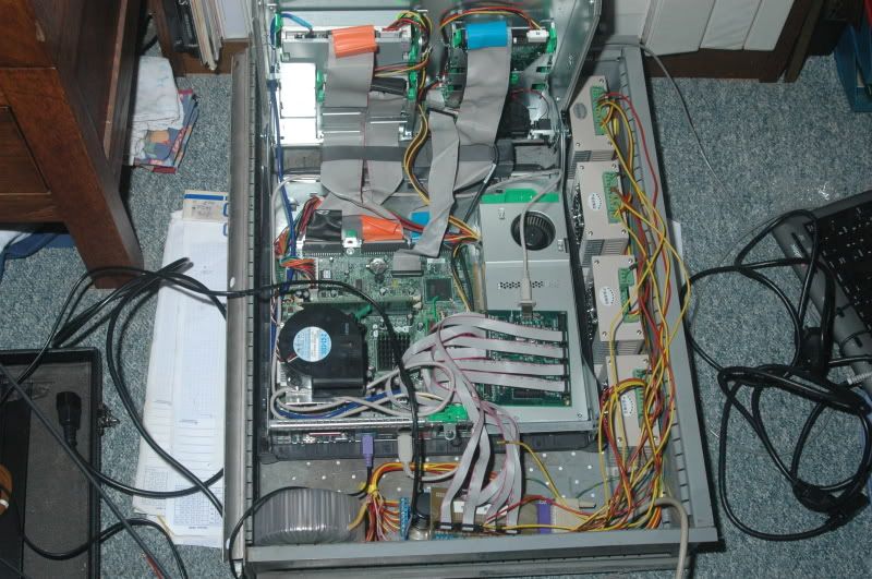
at the moment.. i'm busy wiring the new control PC with the USBCNC board, :stickpoke
a lot of wires, fortunately i had an old printer cable lying around, i cut off the old centronics connector at one end, took an old PC board, and ripped off the parallel port, to solder that onto my breakout board.. furthermore i added 7 10-pin flatcable connectors and soldered the lot..
USBCNC is up and running.. i already dialed in the control, now all i have to do is put the drawer back into the steel cabinet..
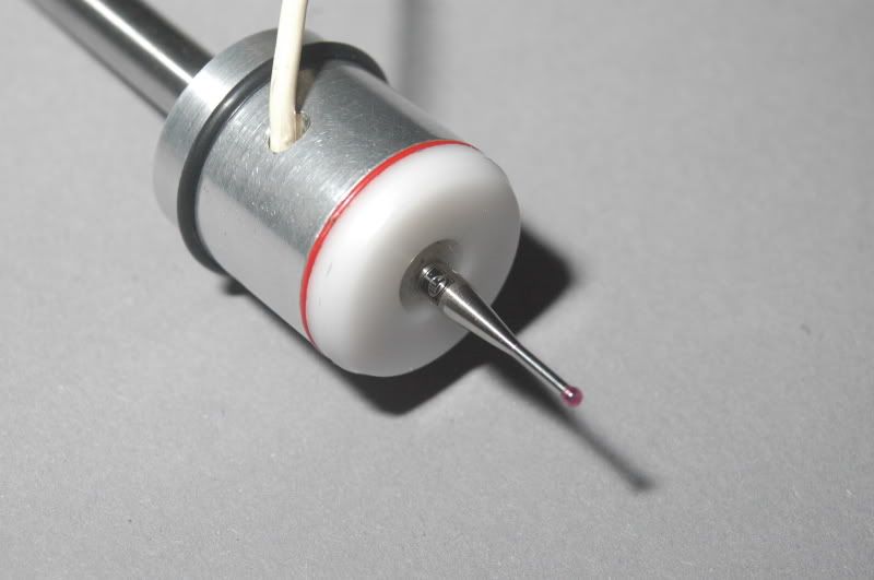
and.. i also bought some ruby-tipped Styli for my touch probe.. plans are.. i'm gonna make some more to sell those..
a tool setter probe will also be available in a while.. basically the same design, but upside down, and with a disc instead of a stylus..
-
01-26-2008, 09:32 PM #243
Member
- Join Date
- Jan 2007
- Posts
- 352
Touch me!!
[ame]http://www.youtube.com/watch?v=OAhlGBAzvq4[/ame]
and
[ame]http://www.youtube.com/watch?v=IxFbIrpwwp4[/ame]
and if you listen closely, you will notice that i'm a fond listener of the Soul Show, a dutch radioprogram that has been broadcast for over 35 years now.. and i've been a listener for as long i have a radio.. :rainfro:
Furthermore.. i'd like to express a Big Thankyou! to Bert Eding, a fellow Dutchman with whom i've been working on the new GUI of his program USBCNC, mach is less expensive, but USBCNC is far more like a professional control, no need for a mouse for regular operation, DXF import embedded, (you might want a mouse here..or a trackball will do )
the layout is very easy to familiarize yourself with.. the F-keys do everything for you..
check www.usbcnc.com for more information.. ( and mind you, we're working on more and more things to go into USBCNC, like automatic probe-functions, and cycle-programming )
-
01-26-2008, 10:46 PM #244
Registered
- Join Date
- Jul 2006
- Posts
- 155
arie that is so neat! I like the idea of having a prove on a mill at home, could make a lot of things a lot easier! maybe this is somthing else I will have to copy from you haha
chris."you don't even need cnc if your handy with a torch"
-
01-26-2008, 11:04 PM #245
Member
- Join Date
- Jan 2007
- Posts
- 352
Chris, you maybe should change your nickname from snowshovelbmx to copycat :stickpoke Originally Posted by snowshovelbmx

better copy my controlsoftware as well, since we're working on a circlecenter cycle as you can see.. and about anything else we can dream up..
-
01-27-2008, 04:14 PM #246
Member
- Join Date
- Jan 2007
- Posts
- 352
[ame]http://www.youtube.com/watch?v=dzRdQG5nEpg[/ame]
since i really can't afford myself a Porsche, i might as well try to replicate my own.. so.. i'm writing some scanning software to do that...
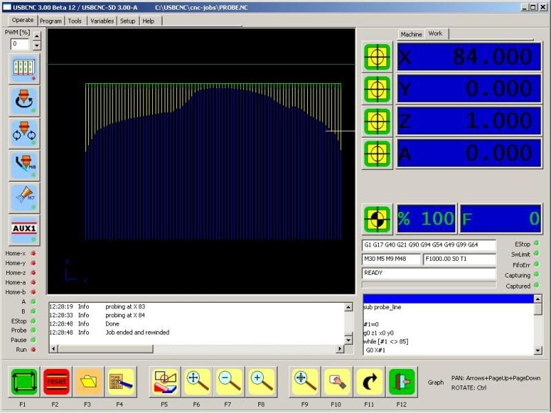
and this is how she looks on screen.. ain't it neat?...
-
01-27-2008, 07:57 PM #247
Registered

- Join Date
- Aug 2007
- Posts
- 6
It looks super Arie! Your new developed software has a real attraction to people who are starting.
Your probe is really something, ready to use and i like the way it interfaces with your USBCNC.
-
01-28-2008, 07:56 AM #248
Member
- Join Date
- Jan 2007
- Posts
- 352
Believe me, this is only the beginning...
at the moment i'm working on an intelligent scanning routine, that's the benefit of working with professionals, Bert Eding the programmer of USBCNC has put some extra's put in for me, to get things done more efficiently
just wait for the next videos... :rainfro:
-
01-28-2008, 01:39 PM #249
Gold Member
- Join Date
- Aug 2006
- Posts
- 1602
Hi Arie, just a quick question - I know you have a high-speed spindle on your lovely little machine, do you ever use it to drill holes of 6mm dia and above, or do you just mill out everything with a smaller cutter?
-
01-28-2008, 04:08 PM #250
Member
- Join Date
- Jan 2007
- Posts
- 352
i've not drilled a single hole larger than 2 mm, but if neccessary, it will be able to perform that..
milling a spiral is far more effective though.. so i'm going to build a cycle for that.. so i can implement that in USBCNC , along with some other often used cycles..
-
01-29-2008, 08:11 AM #251
Member
- Join Date
- Jan 2007
- Posts
- 352
further optimizing of the scan program....
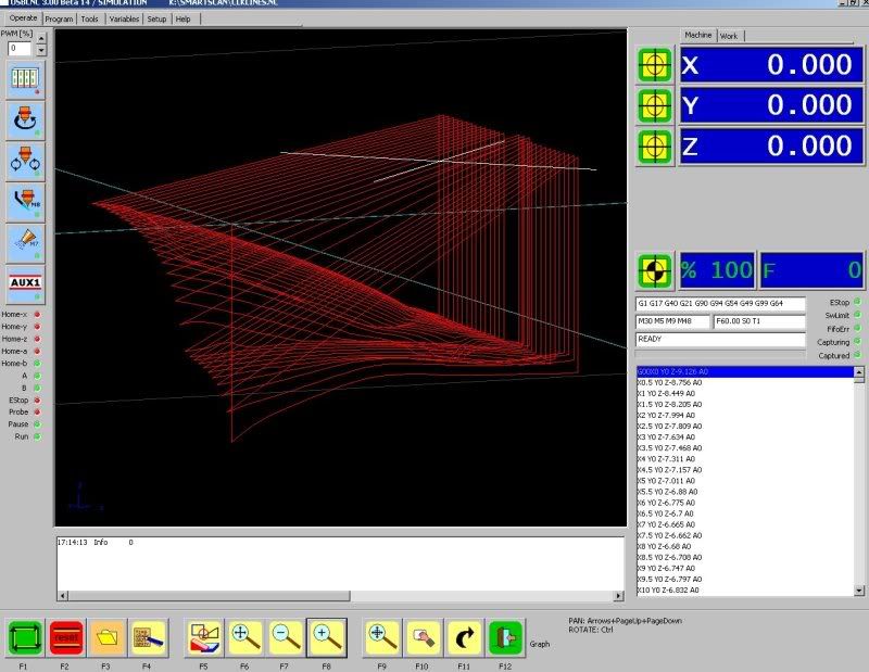
scanning a section of a Mercedes CLK
a 15 x 15 mm section with a 0.5 mm scanresolution
scanning is sort of optimized, the probe first scans vertical, then retracts with a preset value ( scanresolution ) and then scans sideways,
if it touches, it will retract again, and scan sideways, if it doesn't, it scans down
-
02-07-2008, 07:57 PM #252
Registered
- Join Date
- Jan 2008
- Posts
- 59
Would you be doing up any lathe cycles with the probe? Tool offsets or offset checking with the jewels probe. I don know the real term to describe it. But you use the probe to check the diameters of the turned parts to make sure it matches your programmed diameters. and if its off, it changes the tool offsets to compensate. That would be awesome to have with a bench top size lathe.
-
02-07-2008, 08:37 PM #253
Member
- Join Date
- Jan 2007
- Posts
- 352
with the right software, ANYTHING is possible... if you'd put this probe in a lathe, and calibrate it, it can do measurements, and if your software is capable of using the measurements for correcting offsets.. it might just be that easy...
-
02-08-2008, 08:01 PM #254
Registered
- Join Date
- Jan 2008
- Posts
- 59
Sorry. I was referring to USBCNC. Should this be something I should peak to them about? I asked here since you were working with them and your probes.
-
02-08-2008, 09:24 PM #255
Member
- Join Date
- Jan 2007
- Posts
- 352
Originally Posted by Noodles87
Ok.. i see, well.. in USBCNC you can program the probe to measure certain parts, of a workpiece, and by comparing these to parameters, you could make a "GO/NO GO" message, and display the deviations from the nominal dimensions.Sorry. I was referring to USBCNC. Should this be something I should peak to them about? I asked here since you were working with them and your probes.
altering tool offsets this way isn't (Yet) possible, and i do have my doubts if that's a sensible thing to do.
toolsizes should be set once, and if the tool wears, you should replace em.. not alter the offset.. you can't make a blunt tool perform precise operations..
what kind of tolerances are you thinking of anyway?.. the Beagle is capable of +/- 0.01 mm with ease... so if i'm off by more than 0.05mm, really, i should seriously consider checking my tools..
-
02-10-2008, 01:33 AM #256
Registered
- Join Date
- Jan 2008
- Posts
- 59
±0.01mm is the average. And there might be a time for a little higher accuracy once in awhile. But I was mainly talking about checking new programs. Making sure all the offsets are correct. That, or is there a way to implement using the tool offset on a new program. Make sure all is set. And then go about running operations. I noticed it on the haas site and thought I'd ask.
-
03-17-2008, 06:16 PM #257
Registered
- Join Date
- Mar 2008
- Posts
- 201
Arie,
Absolutely magnificent machine. I love the simplicity of it and the fact that everything is surface ground for ultimate precision. Also the fully supported X axis. It really is a tabletop VMC.
I have a few questions.
1) Did you secure the master rail to a edge for location? What I mean by this is, most manufacturers of rails suggest to butt one edge of the master rail against an edge and hold it in place with setscrews or wedges from the other side. If not can you explain the reasoning please.
2) How did you align the axis to each other? For example, how did you line the X rails to the Y ones?
3) Do you plan to add bellows or other covering to protect the ballscrews?
4) Are there any more machining videos or pictures coming?
Thanks for posting such a great thread. I learned a great deal from it.
-Serge
-
03-17-2008, 07:32 PM #258
Member
- Join Date
- Jan 2007
- Posts
- 352
Serge,
i didn't secure the rails to an edge, there's no need for that in fact.
the vertical collumn is accurately positioned at a 90 degree angle to the base ( y-axis rails, those were aligned with a dial indicator along the base.
the same thing goes for the Z-axis
the x-axis bridge rails were positioned along the collumn, also by means of a dial indicator
( guess this covers questions 1 and 2 )
Yes, i do have plans to get some bellows, or cast my own from 2comp. rubber... problem is i didn't really take bellows in to acount when designing.. :withstupi
Video's?.. pictures?.. will do some in the future, i have some stunning things up my sleeve.. :rainfro:
-
03-17-2008, 08:18 PM #259
Registered
- Join Date
- Mar 2008
- Posts
- 201
Thank you for the reply Arie. I'm currently designing an aluminum benchtop mill (Not extrusions) and am trying to absorb as much info from the forum as possible.
It's nice to hear that the master rails don't have to be supported from the side, they are just screwed down. This makes things simpler. Fewer parts to make and less holes to drill.
One more question. Do you ever plan to make your own spindle for this machine? It seems to me that a router designed to cut wood would get a little sloppy over time cutting metal (In regards to the bearings).
I look forward to whatever you have up your sleeve. I'm guessing some pics and vids showing a mould/moulds being milled. High speed 3-D machining.
-
03-17-2008, 08:49 PM #260
Member
- Join Date
- Jan 2007
- Posts
- 352
plans are: either, replace the current router ( which already is upgraded with a more ridgid mounting bracket ) with a more sturdy Kress spindle for the time being..
or replacing it with a Hi-freq spindel with electronic control, putting me back another 1000 euro's..
better save some dough first i guess..

 Reply With Quote
Similar Threads
-
more progress..
By adam_m in forum DIY CNC Router Table MachinesReplies: 0Last Post: 11-26-2013, 03:56 AM -
Design In Progress
By JoeDawg in forum Uncategorised MetalWorking MachinesReplies: 1Last Post: 10-07-2008, 07:48 PM -
My First Router Design & Progress
By watsonstudios in forum CNC Wood Router Project LogReplies: 40Last Post: 07-22-2007, 09:19 AM -
Looking into buidling an Auto-start RPC
By Wendell in forum Phase ConvertersReplies: 2Last Post: 10-12-2006, 03:03 AM -
Alibre design in progress
By xyzcnc in forum Uncategorised CAD DiscussionReplies: 10Last Post: 06-07-2005, 06:49 AM
