


I am trying to think through an idea I have but I am not sure what all options I might have available. Looking for any input, ideas, links etc to help me on my way.
Can the signal from a optical encoder be used to send a stepper motor to a preset location? I realize encoders are used to report position. What I am in need of accomplishing is a way to read the position of a manually adjusted optical focus wheel some 4-5" in diameter and have that position then be sent back to the stepper to index a spindle. I do not need fast motion but I need minature/micro size.
Maybe I need to be looking at optical positioning and some way to set marks an optical eye could read and then send the appropriate pulse to the stepper for indexing.
Any ideas much appreciated. I have not worked with encoders before and not sure what all they are capable of these days.
TIA
Bo
Results 1 to 14 of 14
-
04-08-2008, 03:48 AM #1
 Registered
- Join Date
- Sep 2004
- Posts
- 218
What would it take to use encoder feedback for positioning?
-
04-08-2008, 05:14 AM #2
 Community Moderator
- Join Date
- Dec 2003
- Posts
- 24223
The two pulses from an encoder can be used as step and direction pulses for input into a stepper motor controller, if the encoder is attached to a Hand Wheel.
The commercial hand wheels have a detent every division, these commonly use 100pulses/turn encoders in them.
Any scaling would have to be done by either selecting the correct pulse/turn encoder or by digital circuitry, multiplier/divider circuit etc.
Al.CNC, Mechatronics Integration and Custom Machine Design
“Logic will get you from A to B. Imagination will take you everywhere.”
Albert E.
-
04-08-2008, 12:46 PM #3
Gold Member
- Join Date
- Jan 2006
- Posts
- 2985
using an lsi chip from us digital, you can convert the quadrature from the encoder into an direction and clock signals. It would be pretty easy to use a counter ic to scale down the number of clock counts to get the desired ratio between the encoder and the stepper.
http://www.usdigital.com/products/lfls7083-lfls7084/
http://hyperphysics.phy-astr.gsu.edu...c/counter.html
Matt
-
04-08-2008, 03:44 PM #4
Member
- Join Date
- Aug 2005
- Posts
- 1622
There are some stepper drivers and servo drives that act like stepper motors with encoder feedback. Both types use the encoder to track position at the end of a run, be that step and direction signals, or proprietary programming language via RS-232. The application will depend on how complex of a motion control the system needs are. Straight line point to point would be simple. Once you enter into interpolation of the axi's, then it becomes exponentially complex to have the controller mix signal ratios to follow a geometric path. Which as far as I know, cannot be achieved with a RS-232 fed ASCII drive. Originally Posted by Bowman

This will take some research to find a unit that fits the need, then look around ebay to find it affordable! LOL!
Delta Tau comes to mind. Compumotor and one other that I had seen around the zone, used with EMC2....Ahha?
What application did you have in mind?
DC
-
04-09-2008, 04:14 PM #5
Registered
- Join Date
- Sep 2004
- Posts
- 218
Thanks for all the input everyone I think I have some direction now. Maybe lol.
I will make a rough model of what I am trying to accomplish with a more detailed explaination of how it needs to work if it will work at all and post it here in the next day or two. It really seems like it should be doable to me but I know I am lacking the experience in some areas that might be required to pull it off.
Bo
-
04-09-2008, 10:50 PM #6
Gold Member

- Join Date
- Jun 2003
- Posts
- 3312
It sounds to me like your in search of a non closed loop system? i.e. the indexer has no effect on the optical focus. If so there are a couple of things you need to think about. There are two different types of encoders, absolute and incremenental. Using an incremental encoder to determine absolute position requires a mechanical method to establish a "home" or absolute location. If you are talking of closing the loop with a stepper and encoder, then this becomes more problematic if rates of acceleration and motion are involved.
Phil, Still too many interests, too many projects, and not enough time!!!!!!!!
Vist my websites - http://pminmo.com & http://millpcbs.com
-
04-10-2008, 01:57 PM #7
Registered
- Join Date
- Sep 2004
- Posts
- 218
Correct the indexing stepper has no affect on the optical focus rather the opposite. I started a rough 3D model last night but the wife dragged me away.
Hopefully I will get a picture of the real life current setup and the model of what I am working to accomplish posted here tonight.
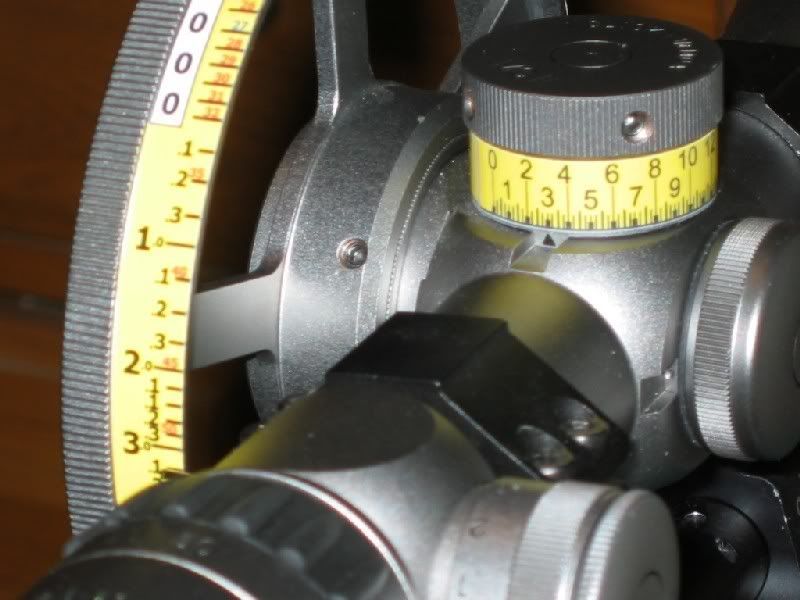
The task I am trying to eliminate is the dialing of the elevation knob on a rifle scope that uses a side focus adjustable objective wheel. This is for air rifles and maybe small caliber rimfire where range finding from shot to shot is critical.
In the sport of airgun Field Target the targets are small metal animals with small kill zone holes from 1/4"-1.5" cut into the face. You have to hit a paddle behind the hole to make the target fall and score a point. The targets are set at unknown ranges and at the moment in order to dial your elevation to the propper setting you have to take a reading off a homemade scale located on the focus wheel then reach over and turn the elevation knob to match for that distance.
My thought is that with some sort of small location sensor or encoder feedback on the focus wheel the signal could be fed to a stepper to index the elevation knob automatically based on the final stop location of the focus wheel. Then when you go to focusing on the target the stepper will always adjust accordingly to the correct distance being read from the encoder.
The focus wheel will not be turning more than 1/2 - 3/4 of a revolution and in some instances for very close or far targets this translates into a little more than one revolution of the elevation knob. Many times it will only need to move a few steps up or down. All of this is done rather slowly so no need for fast speeds or high torque. Trying for small size and low power consumption.
It would be great if each focus distance was equal to the same amount of travel but as the distance gets further out the amount of travel required for the focus wheel gets smaller. IE 10-----------20--------30-----40---50--60 yards.
Thanks again for the thoughts and input. Will post later tonight a better idea of what I want to do visually.
Bo
-
04-10-2008, 05:49 PM #8
Member
- Join Date
- Aug 2005
- Posts
- 1622
To keep it compact, you might consider a simple audio taper potentiometer ratio from the focus wheel to span of the elevation motors feedback linear potentiometer. Al-a-antenna rotating base circuit aka wheatstone balanced bridge?
I couldn't find the basic circuit, but I know I have seen it somewhere out there......maybe my old electronics books. There may be some work in getting the proper ratio, but this would be a very simple circuit. Repeatability? Dunno, but gearing could add resolution and torque!
DC
-
04-10-2008, 10:44 PM #9
Registered
- Join Date
- Sep 2004
- Posts
- 218
I am open to all options but would like to KISS as best as I can. This would have to have good repeatablility to work shot to shot over a 60 shot match.
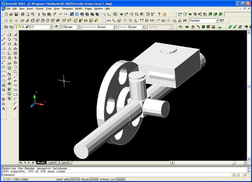
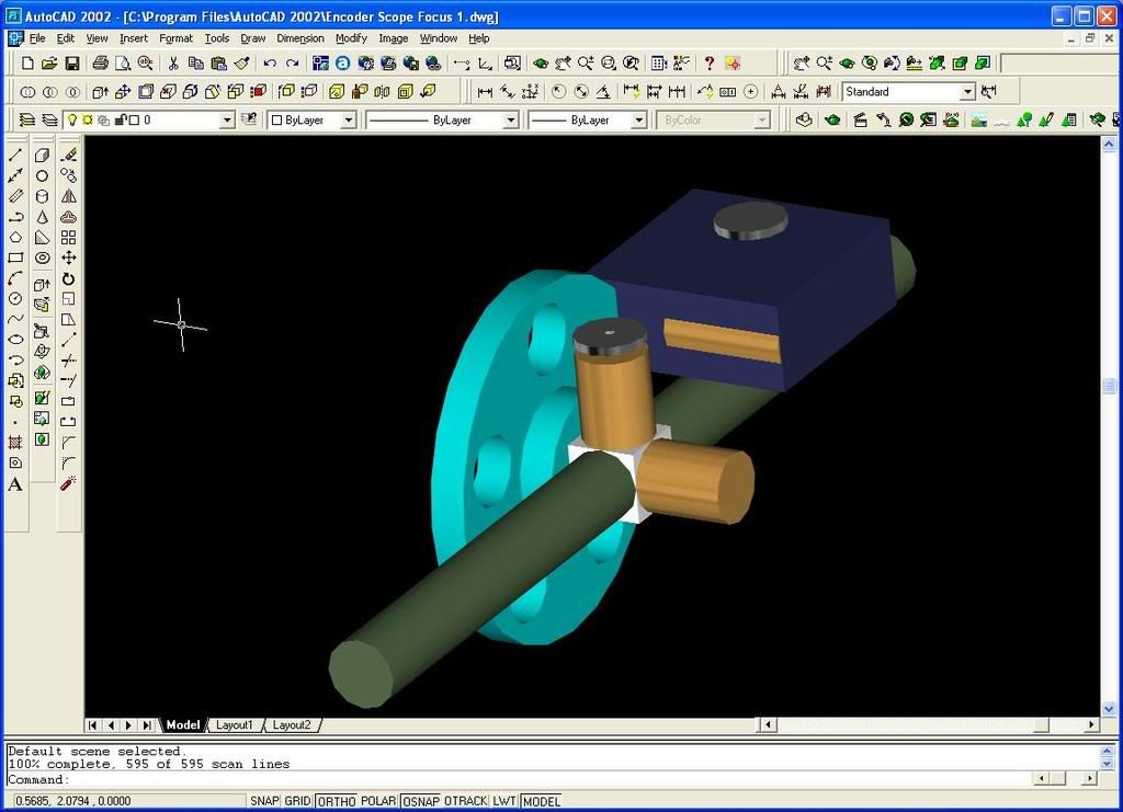
Here are a few screen shots of the rough model and a pic of the actual setup in use now to give you an idea of what I am working with.
Hope this sheds some light on the problem I am trying to work out.
Bo
-
04-11-2008, 05:04 PM #10
Member
- Join Date
- Aug 2005
- Posts
- 1622
Instead of a belt, possibly a small worm wheel gear reduction to adjust the elevation knob?
That would also provide plenty of torque and fine control for repeatability.
DC
-
04-12-2008, 02:35 AM #11
Registered
- Join Date
- Sep 2004
- Posts
- 218
Thats another thought One of Many. Trying to keep it as light as possible but it that was small enough it could possibly even be made of delrin for this application.
This project it out of my scope of knowledge to be sure. I was hoping to come up with the perfect little system that you could simply program the corresponding location of an encoder count to then tell a stepper how many clicks I need it to go for that stop versus another that requires twice as many clicks in the opposite direction. There is plenty of room to put a battery pack and run wiring electronics in the knee riser/rest as well.
Looks like I will just take the couple ideas floated here and ponder the possibilities, do a bit more research.
Bo
-
04-12-2008, 06:17 AM #12
Member
- Join Date
- Aug 2005
- Posts
- 1622
Bo,
I don't know what experience you have as far as creative design, machining or electronics.
From your solid models, I'd say, if you had the internals, I'm sure you would be capable of creating a housing, mounts and mod's to suit.....if you have access to the equipment.
There are toys and other junk(power tools, small kitched appliances etc) out there with worm gear units. All Electronics or a few other surplus outlets may have something you can modify. Don't forget Stock Drive Products for cool little drive requirements. Considering the application and replacement cost of the sights, planning ahead for run-away should be included.
There are PIC servo and stepper drive kits that might suit the I/O with analog and digital capability. There is quite a learning curve in programming what could be a custom non-linear output, that is scaled to the input. Basic Stamps by Parallax at least have PBasic which can cut the learning curve some compared to learning assembler or other high level languages.
You will need to be very conservative with power if you plan to use this under battery power and a stepper motor. Those things still consume power at idle. A PWM servo is much better in that regard.
Looks like a fun project.
DC
-
04-13-2008, 05:45 PM #13
Registered
- Join Date
- Sep 2004
- Posts
- 218
One of Many- You hit the nail on the head with the major part of this for me is the elctronics and programming. I actually have a degree in Industrial Engineering but I never really used it when I got out since I found better money working as a IT/Compliance Auditor than in the CAD/CAM field around here. Trying to rekindle that creative side and get my Sherline CNC mill running again for projects at home. The time and financing is always an issue as well with a kid in college myself now.
I really need to put a design together with the parts I have gathered to make a CNC router for starters as I think it will get my thinking back in line with design. My main focus in college was on CAD/CAM but its been so many years now I sit infront of the computer and go uhh duhh like I have never seen it before trying to remember commands lol.. Basic electronics, wiring things up from diagrams etc no problem. Custom PCB boards and programming etc I haven't a clue but I am sure I could learn
This project would be fun and one thing I never took into consideration you mention is stepper run away ekkkk on a high $$$$ scope that could be ugly.
Thanks again for the ideas. This is one of those projects to file under potential in the future for sure.
Bo
-
04-14-2008, 05:44 AM #14
Member
- Join Date
- Aug 2005
- Posts
- 1622
Bo,
As they say, it's like riding a bike. A little bit of consentration and motivation will put you back in the groove.
If there were a slight chance that this were near linear, I'd recommend a direct gear ratio coupling between the 2 axis. For non-linear, the electronics portion will require a foundation to build on. In that vein, I'd suggest looking into the Parallax BOE or Board of education and/or other development kits they offer. You don't need speed or huge number crunching. There are several kits that would give you a much better idea on the control side, including the I\O expected for the devices you could use in this project and your Sherline.
BOE kit These don't show the books, so that may be seperate now.
IMHO, this really is a worthwhile investment far beyond just your scope project. Microcontrollers are very addictive once you realize what they can be capable of with a little imagination to tame them for your needs.
I have one of the discovery kits. Once I have proven my programs and circuit functional. I transfer it to the OEM kit, which is hard to beat for a $30 customizable device.
Discovery Kit
OEM Kit
Heck, for that matter, I have used the super powerful but really cheap SX28 or SX48 $10 boards with lots of speed and I\O, but you do need to learn their assembly language. This again is where those development kits are very helpful.
Again, I do my prototyping on a development board like this one.
http://www.parallax.com/Store/Microc...me,ProductName
Then download the proven package to the cheap ones!
SX48 Proto Board with servo pad ports
Best of luck.
DC

 Reply With Quote
Similar Threads
-
Emc2 with encoder feedback
By R.thayer in forum LinuxCNC (formerly EMC2)Replies: 5Last Post: 01-27-2007, 04:26 PM -
*** Positioning Problem ***
By baran3 in forum Uncategorised MetalWorking MachinesReplies: 0Last Post: 01-24-2007, 02:25 AM -
g-rex and encoder feedback
By davidp in forum Gecko DrivesReplies: 0Last Post: 04-24-2006, 11:22 PM -
encoder feedback splitter - one to drive one to Mach?
By mgiblin in forum Mach MillReplies: 1Last Post: 03-17-2006, 01:20 AM -
Fanuc O-M positioning
By 723 in forum Uncategorised MetalWorking MachinesReplies: 8Last Post: 07-31-2004, 02:09 AM
