


A billet motor is the way to go i belive but you need to think about cooling, air cooling is the simplest form in a billet engine but watercooling is also possible if you have a bright mind
Thread: Model V8 engine plans required
Results 1 to 20 of 525
Hybrid View
-
02-13-2009, 06:31 PM #1
 Registered
- Join Date
- Oct 2008
- Posts
- 73
-
02-13-2009, 07:14 PM #2
Registered
- Join Date
- Feb 2009
- Posts
- 12
Adaware,
If you know of anyone selling billet V8 plans, please forward that information. I've done an extensive search and email many of the builders (who’s links were posted earlier) but have had no response yet.
-
02-13-2009, 07:29 PM #3
Registered
- Join Date
- Oct 2008
- Posts
- 73
Sorry, don't know of anyone that sell such plans. I'm working on a billet v8 engine drawing myself but each time i fit a new component in the engine it's like opening a can of worms because of the scale and all the parts that needs to be there
-
02-14-2009, 01:41 AM #4
Registered
- Join Date
- Dec 2006
- Posts
- 603
 Originally Posted by Adaware

Where are you at with the drawings?
I am working on the heads of a V8 project. The current design only allows a 8-32 sparkplug.
The block, crank, rods, pistons, camshaft are all done. I need to get the heads done before i move on to the intake manifold.
It will be 5/8 X 5/8 bore and stroke.
-
02-14-2009, 11:06 AM #5
Registered
- Join Date
- Oct 2008
- Posts
- 73
My engine will be a giant compared to yours
What does 8-32 plug mean, 1/8" with 32 threads pr inch?
I first wanted to use the CM-6 from NGK but now i have changed the plans to ME-8 or similiar plug because i couldn't find room for the valves, the idea is to make shure an off the shelve plug fits and then make them myself since they are so expensive.
I currently have a bore of 40mm and a stroke of 30mm so it's about 1:2.5. Have had many 3D models finished but i have redesigned the thing so many times they are not correct anymore so i need to redraw them.
-
02-14-2009, 11:48 AM #6
Registered
- Join Date
- Oct 2005
- Posts
- 73
Woah, that will make an engine of 301.584cc !!!
I want to make, in the distant future, a 4 or 6 cylinder inline engine of about 400cc-500cc capacity. Nothing flash; probably a pushrod operated, 2 valve per cylinder engine with dry sump and water cooling. I like to make engines which I can actually use for something, rather than just display models (though I enjoy the display ones as well, just not as much)
Why such a large bore to stroke ratio?
-
02-14-2009, 01:47 PM #7
Registered
- Join Date
- Dec 2006
- Posts
- 603
Your not from around here are you? Originally Posted by Adaware
#8 thread has a major diameter of 4.16mm and 32 threads per inch. There are vendors at the model engine shows that have plugs that start at 10-32 but 1/4-32 is most popular. You are correct about the money. They are almost 20USD each and the 1/4's are 12USD
#10 = 4.82mm
1/4 = 6.35mm
The picture below is a 1/4-32 next to a production NGK.
-
02-14-2009, 04:44 PM #8
Registered
- Join Date
- Oct 2008
- Posts
- 73
The bore stroke ratio just came by it's own when i found out how big the combustion chamber would be. I plan to make a kind of racing style type engine so the short stroke is not so bad.
I'm from Norway so i'm not so familiar with the inch system as i am with the metric but i guess both systems works well as long as you know both
I will start my own forum thread of my engine project when i have more completed drawings and have the tooling to make the parts.
-
06-09-2010, 09:42 PM #9
Registered
- Join Date
- Dec 2006
- Posts
- 603
Originally Posted by Adaware
Well My plans are complete and I have started to build it. Will take months but will be a fun journey. If all goes well, I will make the plans available in some form or another.
Block 50% done
oil pan 100% done
Heads 80% done
-
06-10-2010, 05:10 AM #10
Registered
- Join Date
- Oct 2006
- Posts
- 708
Another fine looking machine in the making!
Looks large, or is the table small?
-
10-26-2010, 01:01 AM #11
Gold Member


- Join Date
- Feb 2007
- Posts
- 4553

Steve,
Do you have a picture or diagram of how the valve cages fit in the engine and how they work?
Thank You
Jeff...Patience and perseverance have a magical effect before which difficulties disappear and obstacles vanish.
-
10-26-2010, 01:30 AM #12
Registered
- Join Date
- Dec 2006
- Posts
- 603
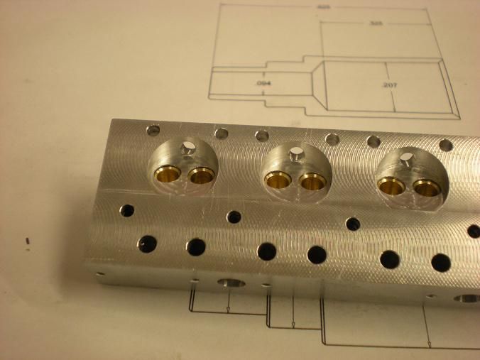
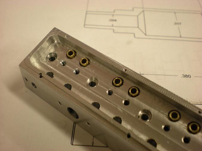
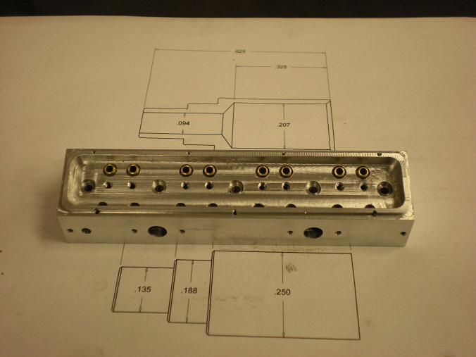
A valve cage is a valve guide, valve seat, and runner passage all in one. The cage is pressed into the head and then the intake or exhaust port is drilled thru into the cage. The fuel flows thru the head and passes thru the valve cage and into the head as long as the valve is open. The exhaust then flows thru the cage and the head to the pipes.
-
10-26-2010, 04:26 AM #13
Gold Member
- Join Date
- Feb 2007
- Posts
- 4553

Steve,
I am assuming the reason for using valve cages is being more durable than aluminum and not having to replace the entire head if the guide or seat wears out.
Thank you for the detailed explanation.
Jeff...
P.S. the parts look awesome!Patience and perseverance have a magical effect before which difficulties disappear and obstacles vanish.
-
10-27-2010, 12:36 AM #14
Registered
- Join Date
- Dec 2006
- Posts
- 603
Hello All!
Spent the afternoon pressing in all the valve cages. I made s simple drive dool slightly smaller than the ID og the cage and pressed them in a drill press. I like the fact that the press fit does not need to be very tight because the cage cant be shot out by the compression of the cylinder.
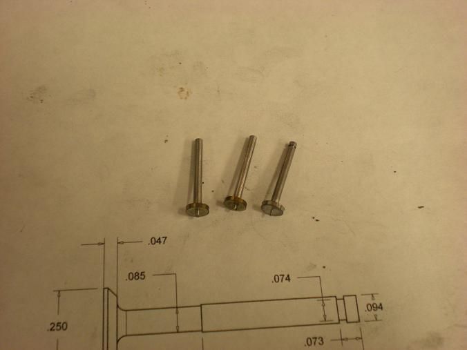
I also started to make some valves. These wont go as fast as the cages.
Stand By!

 Reply With Quote
Similar Threads
-
Engine Plans
By nzer in forum MetalWork DiscussionReplies: 1Last Post: 08-03-2012, 05:14 PM -
I.C. engine plans
By cumminsman in forum I.C. EnginesReplies: 7Last Post: 04-10-2012, 11:43 PM -
Does anyone have any good jet engine plans?
By flyguy1254 in forum Hobby DiscussionReplies: 18Last Post: 04-16-2010, 10:28 AM -
Jet Engine plans
By godspeed in forum Hobby DiscussionReplies: 3Last Post: 05-18-2007, 11:34 AM
