


Interesting chain. The stuff I've seen is made from mostly one type of link; one end is the wide, outside link, and the other end is like the narrower, inside link. Each link snaps inside the next, with special end connector links for bolting down the chain.
Thread: DIY Cable Carrier
Results 161 to 180 of 277
-
01-25-2009, 05:30 AM #161
 Registered
- Join Date
- Mar 2006
- Posts
- 474
-
04-06-2009, 06:26 PM #162
Registered
- Join Date
- Nov 2006
- Posts
- 46
Importing energy chain design
Hi,
Does anyone know how I can get gadman58's dxfs into Solidworks? I only seem to be able to get a 2d sketch rather than a 3d model, despite playing with all the options in the Solidworks import wizard.
Thanks!
Luke
-
04-06-2009, 06:34 PM #163
Registered
- Join Date
- Dec 2007
- Posts
- 37
Luke
In this case it is just a 2d dxf, I will look for the model and send you a stp file.
I had redone it in Inventor.
Thanks
Glenn
-
04-06-2009, 07:08 PM #164
Registered
- Join Date
- Dec 2007
- Posts
- 37
Stp file of chain parts
Here are the stp files for the chain parts
Glenn
-
04-06-2009, 07:55 PM #165
Registered
- Join Date
- Nov 2006
- Posts
- 46
Brilliant, thanks.
-Luke
-
04-08-2009, 12:04 AM #166
Registered
- Join Date
- Aug 2006
- Posts
- 225
To insert into solidworks and make a 3d file from it:
Step 1: Open the 2d dxf in autocad or other 2d viewer.
Step 2: Select the components you wish to turn into a 3d part for assembly. Copy or cut the dxf lines using hotkeys or menu.
Step 3: Open solidworks and start a new part file.
Step 4: Using hotkeys or menu, paste dxf lines. It will prompt you to add to new sketch or alternitively if you have already started a sketch on a plane it will add it. Adjust/scale to your size and modify to suit.
Step 5: Extrude the drawing (or follow steps to get to final shape) and enjoy your 3d part. Now just copy all the other pieces into a new part file and create that cable assembly.
Daniel
P.S Attached is the cable chain i turned into a solidworks file. It is easy to make this into a moving piece inside of solidworks using mates. This piece can ben using physical move. Easy to modify to suit your needs too. Now i just need to stop doing work for others and sit down and cut some cable chain for my machine.
-
05-15-2009, 11:13 PM #167
Registered


- Join Date
- May 2005
- Posts
- 925
I edited Ger21 files so they are machinable from a sheet of 6mm or 1/4" using just a 1/4" endmill

(batmanesque isnt't it? )
)
Attached are the SW files and also added to the zip file the coreldraw drawing I used to adapt ger21 files
Pablo
-
10-03-2009, 02:32 AM #168
Registered
- Join Date
- Oct 2006
- Posts
- 975
ABS pipe cable carrier links
Hello,
I am building a small CNC router/mill and thought I would try and make a cheap alternative for a cable carrier chain(about $3-$4 for 10' of pipe). My first designs were with flat material and I planned to form them from one piece and snap each link together, but I then thought of using material that was already in a closed shape. Plastic pipe is readily available and fairly cheap, so I designed the links to be cut from ABS black plastic pipe. I have made 3" and 2" lengths and the links have projections at one end with a mating hole at the other end. This way every link is the same and they snap together very securely. I still need to attach a length to a machine axis to see exactly how well it works, but this seems to be a viable alternative to buying the cable carrier chains. These links are made from 1.5" ABS pipe which is actually 1.906" OD and close to 1.6" ID. It should not be hard to scale the vectors and use a smaller or bigger pipe that fits the need. Take a look and let me know what you think or if you have questions.
Regards,
[IMG] [/IMG]
Regards,
[/IMG]
Regards,
Wes
-
10-03-2009, 12:36 PM #169
Member
- Join Date
- Apr 2007
- Posts
- 8082
Now, that's some real "thinking outside the box" design. Originally Posted by metalworkz
 Looks like the cuts are at 90 and 45 degrees. Band saw type work. What tool did you form the pins with? Something shop made?
CarveOneCarveOne
http://www.carveonecncwoodcraft.com
-
10-03-2009, 04:45 PM #170
Registered
- Join Date
- Oct 2006
- Posts
- 975
Hello CarveOne,
The pins are done with a pocketing toolpath and a .125" dia. end mill. The profile is being cut with a .25" dia end mill basically because it is long enough to cut almost 1/2 the diameter of the pipe and small enough to fit the radius' used. Toolpahs done as 2 sides.
It is my own design and I used Vectrics Aspire software to draw the parts and create the toolpaths. All the toolpaths are simple 2D toolpaths, although it did take a couple of tries to get the setup on my CNC mill correct. I have toolpaths for each side and cut the links in 2 opposing sides with tabs included to help stabilize the part for cutting. It is a simple matter of cutting off and cleaning up where the tabs are located, and then I mill the inside of the female connector tabs in my manual mill. Ream the holes to fit the projection on the male end and little deburring and the link is done.
I do believe the general shape could be done with basic hand tools(drill, hacksaw, dremel, etc) and the design could be modified to use hardware at each link joint so the projection would not be needed and the links could be made by hand for the person who did not already have a CNC machine.
I have some pictures of the setup in the SX3 mill if anyone wanted to see it. Nothing fancy basically a fence with a pin stop to locate the pipe when rotated. In the picture below there are 2" links to the left and at the right are the 3" links(2ea) I cut for the toolpath test.
Regards,
[IMG] [/IMG]
Regards,
[/IMG]
Regards,
Wes
-
10-03-2009, 06:52 PM #171
Member
- Join Date
- Apr 2007
- Posts
- 8082
Yes, photos of the SX3 setup please. Also a video if you have it.
CarveOneCarveOne
http://www.carveonecncwoodcraft.com
-
10-03-2009, 07:26 PM #172
Registered
- Join Date
- Oct 2006
- Posts
- 975
Hi CarveOne,
I don't have a video, but I can post a picture of the setup in the mill. I will probably be going out to cut some more links today, so I may try to get some video clips if possible.
I will probably be taking the carrier link setup out today to do some 3D toolpaths on a nameplate/guard for my SX3 mill.
I am cutting the full length(10' long) of the pipe and the end is supported with a stand while it is overhanging the mill. The toolpaths are not very big so there doesn't seem to be any problem with the pipe overhang movement. I have just been cutting one link, cut the finished piece off and reposition the pipe for the next part. It would be quicker to do several parts on one side and then rotate for the other side, and finally cut the profiles pin stopping off of the drilled holes, but my setup is working very good as is so I will just need a few more links before taking the setup out.
Regards,
[IMG] [/IMG]
Regards,
[/IMG]
Regards,
Wes
-
10-03-2009, 08:34 PM #173
Member
- Join Date
- Apr 2007
- Posts
- 8082
Very nice! Thanks for going to the trouble to show us.
CarveOneCarveOne
http://www.carveonecncwoodcraft.com
-
10-15-2009, 01:44 AM #174
Registered
- Join Date
- Sep 2009
- Posts
- 30
Man, I'm lagging like 2 years on this thread, no wonder I get nothing done. Just ran into some pics the other day of Big S's setup, great stuff. I always believed that if you live where there's honey the brain goes all inclusive on you and takes off to Dominican Republic. Thank God for lack where books still work and there are folks like Big S. Got my ass thinking....
Here's a little DXF for a smaller snake out of 1/8" material. The snap in parts have a tolerance of 0.002", that is the standard for a press in but just to make sure you can add a 1/16" clearance hole for some screws instead of glue. Swivel A has a hole and Swivel B is a stud, two different diameters, best way to remember is "B stud likes A hole"....
-
11-13-2009, 10:13 PM #175
Registered
- Join Date
- Dec 2008
- Posts
- 4
cable carrier from a dredger
Hi gentlemen: I am working in a dredger and I have found this system... It looks quite simple to copy, isn't it? Yours: Ruben
-
11-17-2009, 01:56 PM #176
Registered
- Join Date
- Dec 2008
- Posts
- 4
The piece that is in the middle has a different shape that can be seen en the next photo. Originally Posted by Rubeno
-
11-17-2009, 02:47 PM #177
Registered
- Join Date
- Nov 2009
- Posts
- 1
Hi Ruben,
to my opinion it is a lot of work to copy this cable carrier. Did you know that igus has very cheap solutions and does also send free samples? Check www.igus.eu or let me know if you have questions!
igubart
-
11-17-2009, 04:38 PM #178
Registered
- Join Date
- Dec 2008
- Posts
- 4
Hi Igubart: Thanks for your information. It looks pretty nice.
-
12-03-2009, 01:10 PM #179
Registered
- Join Date
- Aug 2005
- Posts
- 437
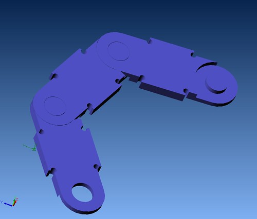
Hello guys, thought I’d post a quick pic of an Echain I’ve been toying with. Still early in the design and I’m not too sure I like the idea of having to machine on both sides of the link sides.
Rob.

Deeds not words...
VoltsAndBolts runs RC for the builder. http://www.voltsandboltsonline.com/ My Forum
-
12-07-2009, 07:28 PM #180
Community Moderator

- Join Date
- Mar 2004
- Posts
- 1661
Here's one I did, it will only allow a movement between 0 and 30 degrees. We've made them in both polycarbonate and plywood. The "cross stringer" is glued. I cut a long "ditch" in a piece of wood like a jig and let the sides stand there while the glue was hardened. I've cut it in both 4 and 5 mm material and it's pretty nice and sturdy in both.
The G-code runs fine in EMC2 (metric settings). Use a 5 mm flat end mill zeroed at the bottom of the work piece and you're good to go.

 Reply With Quote


Similar Threads
-
DIY cable carrier
By sixtyeight in forum MetalWork DiscussionReplies: 1Last Post: 12-18-2018, 08:47 PM -
DIY Cable Carrier
By rogerquin in forum VideosReplies: 86Last Post: 05-12-2018, 03:22 PM -
Cable carrier
By Gamble in forum TorchmateReplies: 2Last Post: 07-31-2014, 03:21 AM -
AC power cable in the same cable carrier with motor cables
By bandtank in forum CNC Machine Related ElectronicsReplies: 12Last Post: 06-02-2010, 12:06 AM -
Cable carrier competition: The way you use your cable carriers could earn you a cash
By igus in forum News AnnouncementsReplies: 0Last Post: 01-22-2010, 07:06 PM
