


they are DCOriginally Posted by JHCHOPPERS

Thread: My new pair of SL-1s!
Results 21 to 40 of 86
-
04-17-2009, 03:37 PM #21
 Registered
- Join Date
- Mar 2006
- Posts
- 67
-
05-19-2009, 10:40 PM #22
Registered
- Join Date
- May 2007
- Posts
- 100
Have you started on your conversion to Mach3 yet?
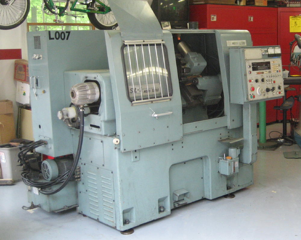
I just got my SL-1, it looks even better than I expected it too.
-
05-29-2009, 01:20 AM #23
Member
- Join Date
- Oct 2005
- Posts
- 420
Mori wiring diagram
In case anyone is still in need of a wiring diagram. I have one for an SL-3 w/ Yasnac 2000G single line display. Click the link to the doc file.
http://www.box.net/shared/ceznmopsg4
Hope this helps.
-
11-10-2009, 10:03 AM #24
Registered
- Join Date
- Jun 2005
- Posts
- 476
That's a clean looking lathe! Do you plan to run it as-is, or to retrofit? Originally Posted by JHCHOPPERS
Since my last post, I've been too busy at work to set foot in the shop and work on my Moris. I carved out a few hours to install a 10hp rotary phase converter in the garage and start clearing space around the lathes.
Hopefully, I'll be able to get the SL-1H powered up soon - it's the one with working controls. The other one will have to wait a little longer, although the thought of being able to make chips on at least one lathe is getting me excited about doing a proper Mach retrofit!
-
11-10-2009, 10:05 AM #25
Registered
- Join Date
- Jun 2005
- Posts
- 476
Wiring Diagram
Thanks for sharing! I have this same manual and when I first saw it, I marveled that it was hand drawn! Originally Posted by nlh
-
11-10-2009, 04:09 PM #26
Registered
- Join Date
- May 2007
- Posts
- 100
I plan to do a complete conversion to Mach3. The shop has only signal phase 220VAC so I plan to use a VFD for the main spindle and new DC servo drivers and new digital encoders. Originally Posted by damae
Haven’t done anything to it yet, as we are currently doing a complete conversion on a Bridgeport VMC in our spare time.
-
11-10-2009, 06:26 PM #27
Registered
- Join Date
- Jul 2005
- Posts
- 14
Do you know if it is possible to do a conversion using the original spindle drive and x/z servos?
Keith
-
11-10-2009, 10:04 PM #28
Registered
- Join Date
- May 2007
- Posts
- 100
Yes, however you will need to interface Mach3 to the Spindle Drive. It is most likely a analog system (+-10VDC for the control), so you will need spindle driver board like the following (not 100% sure on that): Originally Posted by kek_63
http://www.cnc4pc.com/Store/osc/prod...products_id=58
The servos are DC and the drivers are analog control. SO, the servo motors are good for a retrofit, the trick here is to get the analog drivers switched to Step/Dir (pixie P100 boards) or change the drivers to something like: Originally Posted by kek_63
http://www.shop.cncdrive.com/index.php?productID=166
Hope this helps
JH
-
11-14-2009, 10:30 PM #29
Registered
- Join Date
- Jun 2005
- Posts
- 476
It's been a while, but I finally installed a rotary phase converter and ran power to the first of the two machines, the SL-1H.
Lessons learned:
1. Door switch! The machine will appear dead if the service panel door is opened.
2. If you're going to run the machine without a tailstock, the lines must be capped! My first attempt had all of the fluid pumping straight into the coolant drain!
3. Capping the hydraulic lines to the missing tailstock is a temporary measure. They are still slowly leaking fluid into my coolant drain.
It was a great thrill to see the machine come to life! Very satisfying to jog the axes around with the MPG and see the toolchanger working! I'm sure it would have been great comedy to watch my facial reactions as I fumbled my way through the controls, trying to figure everything out.
So far, everything is working except the spindle. I'm looking for suggestions, especially the obvoius kind. Some of the switch labels are worn and I am not sure what some of the switches do... it's entirely possible there is a "disable spindle" toggle I missed somewhere.
Any ideas?
-
11-14-2009, 11:12 PM #30
Member
- Join Date
- Oct 2005
- Posts
- 420
What control does this machine have?
I setup and run an SL-1 w/ a Yasnac 2000G control and no CRT on a near daily basis. I may be able to give you some pointers.
-
11-15-2009, 03:35 AM #31
Registered
- Join Date
- Jun 2005
- Posts
- 476
The first machine is a SL-1H with Yasnac 2000G control with CRT. The second machine (which doesn't have power wired to it yet) is a SL-1A, also with a Yasnac, but with the single-line display. Originally Posted by nlh
I recently wired-in a rotary phase converter -- I might have the phase rotation wrong. Don't know how important that is.
-
11-15-2009, 05:20 AM #32
Member
- Join Date
- Oct 2005
- Posts
- 420
Phase rotation is very important. If it is not correct, your pumps (coolant/hydraulic) will turn backward, that is, if the machines turns on at all. In my experience with my SL-1, if phase rotation is incorrect the machine can still be powered up but will be in permanent alarm mode until phase rotation is corrected.
I would say your phase rotation is correct if your able to perform tool changes and the tailstock lines are pumping out oil.
On my machine to turn the spindle on in manual mode, first the chuck needs to be clamped, make sure your MODE knob is turned to a setting that will allow manual movement (usually anything other than EDIT, MEM/AUTO, TAPE, or MDI). Then depress the spindle forward or reverse button and use the spindle speed knob to control rpm.
Another thing to try to get your spindle turning. Put the mode selector knob in MDI mode, the input M3 and S(rpm of your choice) and then push cycle start.
Keep in mind all of this may be slightly different with your 2000GII crt control. I have no experience with that particular variant. However it should be close.
Hope this helps, good luck!
-
11-16-2009, 12:11 AM #33
Registered
- Join Date
- Jun 2004
- Posts
- 236
A bit of advise on running these old Moris on Phase converters. Make darn sure
the taps are correctly set on the transformers in the rear cabnets.
If not, the Spindle drive can blow making the machine nearly worthless.
Spindle drives are the weak link in those machines. If your not sure
how to check the taps, have a qualified tech check them for you
Wayne
http://nosala.com/
-
11-16-2009, 04:45 PM #34
Gold Member
- Join Date
- Feb 2009
- Posts
- 6028
Sl1
And after you have completed the above items, press the foot petal for chuck clamp.
-
11-16-2009, 05:50 PM #35
Member
- Join Date
- Oct 2005
- Posts
- 420
Yes, don't forget the foot pedal! lol
Any luck with it today?
-
11-16-2009, 09:09 PM #36
Registered
- Join Date
- Jun 2005
- Posts
- 476
Unfortunately, I still can't get the spindle going. The more I play with the controls, the more I realize I need to read through the operator's manual. I suppose I should have expected MDI mode to be very different from Mach, which I ran on my Bridgeport Series I mill. Originally Posted by nlh
I'm down to three likely causes:
1. Blown spindle drive (caused by installing 3 phase power wrong)
2. Stuck button on the control panel. Some of the buttons are a bit gummy. Spindle FWD is missing the plastic cap, although I can push the plunger with a pen.
3. Operator Error (Not knowing how to turn on the chuck clamp, for instance)
If I haven't blown the spindle drive already, then switching the phases would be one way to guarantee I did. =) The manuals I have don't have any instruction about how or where to adjust the taps. I need to take a closer look at the wiring schematic.
So I have two choices:
Option A: Hope that the phases are wired correctly and work through the list of things that could cause a normally functioning spindle to not turn on.
Option B: Assume that the phases are reversed and try switching L1/L2. I see this as more of a last resort.
-
11-16-2009, 09:17 PM #37
Registered
- Join Date
- Jun 2005
- Posts
- 476
Option C
There's also an Option C: Tear down and retrofit.
-
11-16-2009, 09:23 PM #38
Registered
- Join Date
- Jun 2004
- Posts
- 236
Are you getting any alarm codes? or is the spindle just not turning on?
You can swipe a plastic button off the tailstock funcion on you control
panal if you are carfull, They just snap in
There should be a lamp with the image of a chuck on the panal
that should be lit, that tells you chuck is in clamp position
or the spindle will not turn on
also, if the turret functions manually, you have hydrolic pressure.
If you have hydrolic pressure, Your phasing should be correct.
Wayne
-
11-16-2009, 11:21 PM #39
Gold Member
- Join Date
- Feb 2009
- Posts
- 6028
SL1
If you can index the turret the hydraulic pressure is ok. Backwards phase will not take out a SDU, nor make it run backwards. If the drive has a power lamp on and no alarms, you have something else interlocking it. Spindle clamp ( make sure the key switch is on od and the tube is back.) tailstock interlock (if it has one) barfeeder interface (did it have a barfeeder?) etc.
-
11-17-2009, 04:18 AM #40
Registered
- Join Date
- Jun 2005
- Posts
- 476
Checklist
Thanks for the checklist guys! I really do appreciate your help!
Checked:
-Spindle Clamp (good - light comes on)
-Hydraulic pressure (good - turret clamps and indexes)
-Alarms cleared (yes)
-Tool changer works
Stuff that I need to check:
-Power light on drive. Is this light on the Versadrive in the control cabinet?
-Spindle clamp ( make sure the key switch is on od and the tube is back.)
-Tailstock interlock. I'm not sure how to check this.
-Barfeeder interface. Yes, it had a barfeeder, but I don't know what to check.
Wayne, thanks for the suggestion to swap buttons.. I think I can steal one off my other SL-1 for now.
I'll investigate a bit more tonight and report back. Thanks again for the helpful comments!

 Reply With Quote
Similar Threads
-
How to pick a pair of calipers
By peetle in forum Calibration / MeasurementReplies: 16Last Post: 03-28-2009, 01:50 AM -
Anybody Need A Pair of IH Optical Limits?
By SCzEngrgGroup in forum Charter Oak Automation Support ForumReplies: 0Last Post: 12-03-2008, 09:08 PM -
Twisted wire pair for step & dir wiring?
By patdttr225 in forum Gecko DrivesReplies: 8Last Post: 04-09-2008, 03:27 PM -
Pair of 1200oz-in steppers for sale on eBay
By Apples in forum Australia, New Zealand Club HouseReplies: 1Last Post: 02-25-2007, 02:49 AM -
Well looks like I've stuffed up a pair of 1200oz-in steppers. :(
By Apples in forum Stepper Motors / DrivesReplies: 11Last Post: 01-30-2007, 12:11 PM
