


I finally got around to building a plasma table after putting it off for years due to an off-roading habit. The machine has been in the design phase for the last month as I read over a few dozen build threads on here plus some help from an co-worker built one a few months ago. The one thing that throws a monkey wrench in the requirements since sooner or later I would like to add the ability to use a router on the table for wood or plastic.
A few parts I have already started to collect. I did manage to get two different pairs of THK linear rails.
Y-axis rail - THK SSR25 for 280 shipped. 2x1830mm rails with 2 carriages.
X-axis rails - THK SR30 for 280 shipped. 2x2070mm rails with 2 carriages. Not sure how I won the Ebay auction considering the price was 600 but I only offered 250; talk about over kill for plasma tables considering the specs for the units. The rails are drilled for bolts thru the top. Both sets of rails came from the same company on Ebay.
Machine specs so far
- Candcnc dragon cut package (still need to purchase)
- Linear rails
- K2cnc floating Z
- Water table (Air bladder design)
- Rack and pinion
- 2 x 6ft racks from Moore Gear with drilled and counter bored holes.
- Dual X-axis drives
- Single Y-axis drive
- Maybe CNCrouterparts.com R&P drives. Debating if the time and cost to make the units outweighs just buying them for 90 dollars each. So far I’m leaning towards buying.
Gantry design
- $108 for 72inches - 80/20 Inc – Series 40 80mm by 80mm T-profile
I purchased some econ nuts and a few nuts that align in the T-slot for aligning the rail to be parallel with the slots.
- Going with the 4” – 6” floating Z head from k2cnc (still need to purchase)
- 6ft Moore Gear rack with drilled and counter sunk holes.
- Debating between ¼ steel end plates or ½ AL plates. I will be using a gusseted design which I will post later tonight. Probably will go with steel so I can just mig weld the pieces.
- There is a part of me that wants to use a rail on top and side of the T-profile but not sure if it is needed.
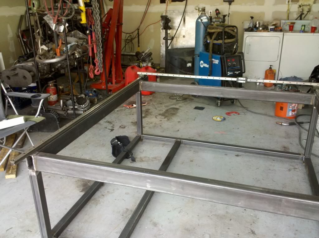
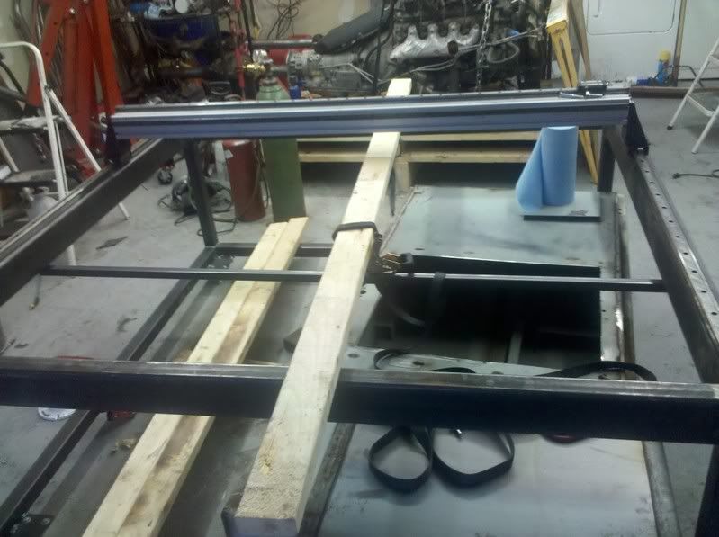
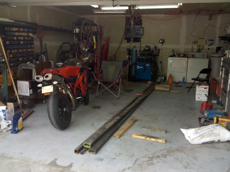
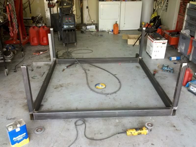
Metal for the frame. Dang I really should clean the garage fully but hopefully soon the engine will be gone from the corner and also the 1 ton axles.
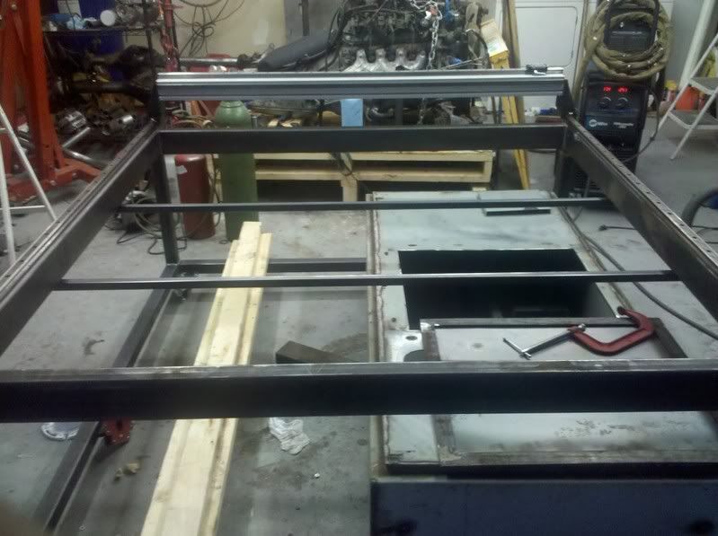
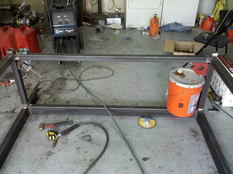
Compared to others I did the build a little backwards. I wanted the top flat in the same plane so I squared the top off and made the pieces flush before flipping over to start on the legs.
The bracing height was set by my little helpers. Mr. Magnet and Ms. Pail
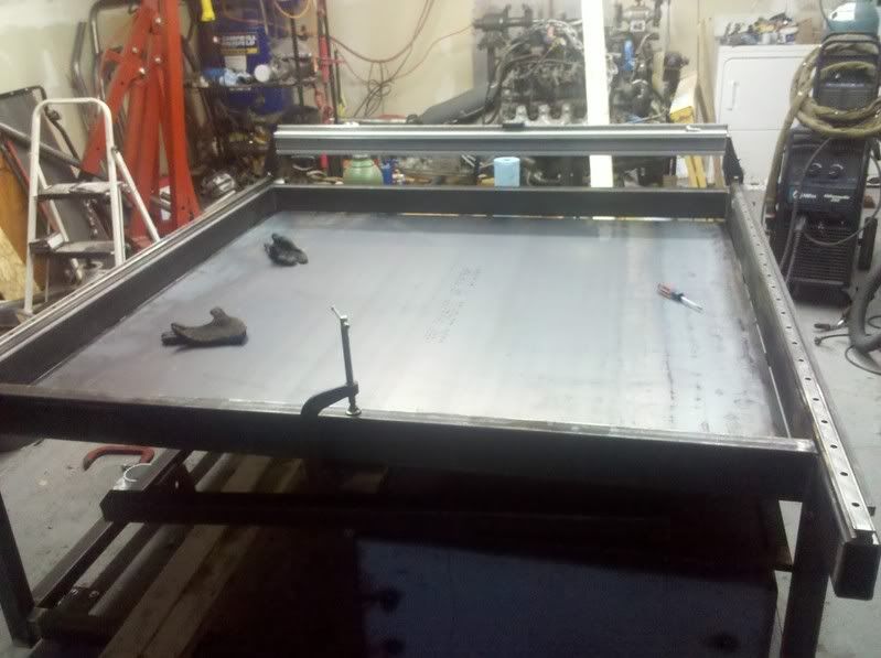
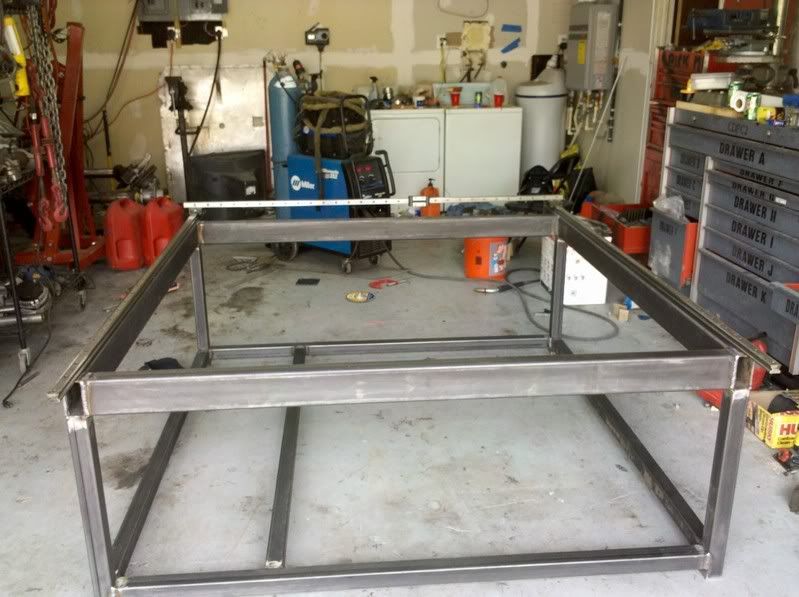
All finished with the main frame. Not bad for 3 hours worth of work. I still need to weld the slate holders on and purchase the sheet metal to seal the pan up.
Thread: 5' x 5' plasma table
Results 1 to 19 of 19
-
07-05-2011, 07:29 PM #1
 Registered
- Join Date
- Oct 2010
- Posts
- 57
5' x 5' plasma table
-
07-09-2011, 08:51 PM #2
Registered
- Join Date
- Oct 2010
- Posts
- 57
Slowly the parts have been arriving. Sorry for the crappy pictures but my good camera got stole in May when my house was robbed.
List of parts from McMaster so far. Some of the quality was a little high due to the box size but it was still cheap. All bolts are socket head grade 12.9 and blue to tell they are metric. I stayed with metric since the THK rails, T-profile, and a few of the other parts were. Just easier to stay metric.
M6x1.0mm 30mm: 2-50packs at 10.96 each
M6x1.00mm 20mm:1-50 pack at 9.96 each
M8x1.25mm 25mm: 1-50 pack at 13.28
M8x1.25mm 16mm: 1-50pack at 11.58
6x1mm tap: 2 of them at 6.25 each
8x1.25mm tap: 2 of them at 6.82 each
5mm jabber drill bits: 10 of them at 1.65 each
Swivel level mount with stud 3/8-16 thread , 3750lb load each: 4 of them at 6.80
16oz tap magic: 9.69 each
Total: around 150 with shipping
Multiple drill bits and taps were ordered since no normal store will carry metric taps. Had I ordered just one it probably would have broken right away.
For the cable carriages I went with IGUS off ebay. The company I went thru for the THK rails happen to be selling these also so I did the "make offer" option and got them for half off with combined shipping. Company was automation_wholesale. They are quick to ship and good to deal with so far.
Igus 27.07.075 Cable Carrier 82" With Ends (505)
Igus 27.07.075 Cable Carrier 80" With
$78 dollars shipped for both.
One of the E-chains were missing the mounting bracket at the end
P/N 260-12
$20.12 shipped for two sets of brackets I think. Not sure if each set was for one cable or just an end so I ordered two off ebay.
-
07-09-2011, 08:52 PM #3
Registered
- Join Date
- Oct 2010
- Posts
- 57
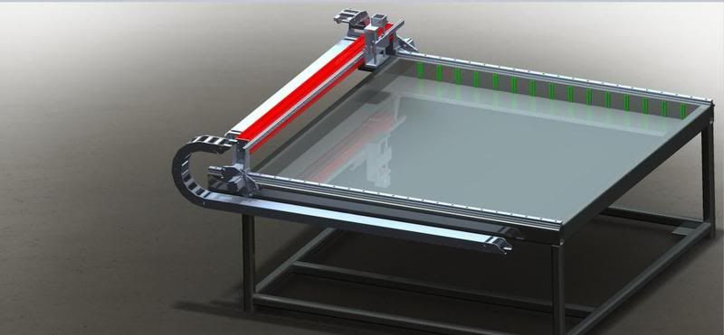
Simple cad model of the table so far. Slate holder design will be changing to just a flat plate with slots cut into to hold the slates.
Time for the fun of drilling and tapping a crap load of holes.
Steps followed.
1. Place linear rail where needed and clamp down
2. Use a transfer put to make the first hole on one side.
3. Removed rail to drill and tap this hole
4. Replace rail and in the process bolt down the one side and line back up rail to punch the far side.
5. Repeat process again
6. Then bolt the rail back down to transfer punch the remaining holes for drilling and tapping.
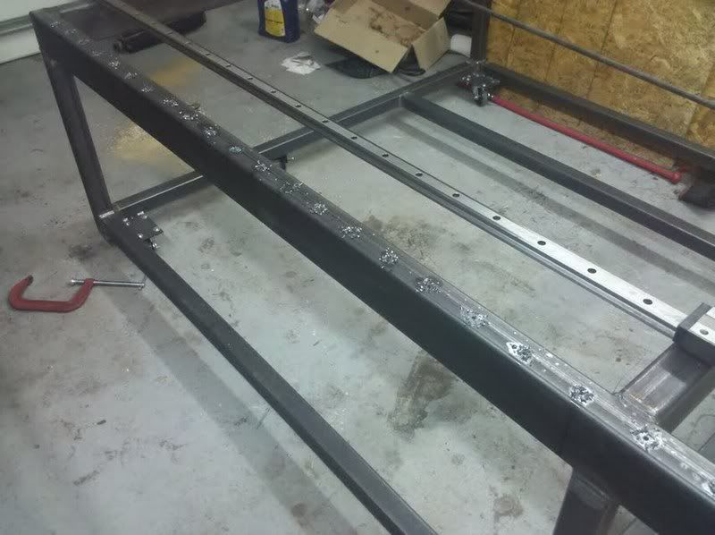
Even with following those steps there wasnt much room for error with these rails. I would say drill the holes bigger but its heat treated and harden rail. Good luck doing that so better make it right the first time. To save time I used a technique for tapping suggest to me by a old timer. Chuck the tap up into a hand drill and place on the slowest setting, came more true and alot quicker. A little tap magic was used for drilling and tapping to help in the process.
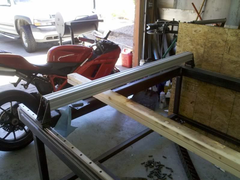
Gear racks were also installed. I just lined them up with the seam in the metal tubing. I may need to shallow head socket screws from McMaster to avoid hitting the drive units. I'll added it to the list of crap to order from McMaster later on.
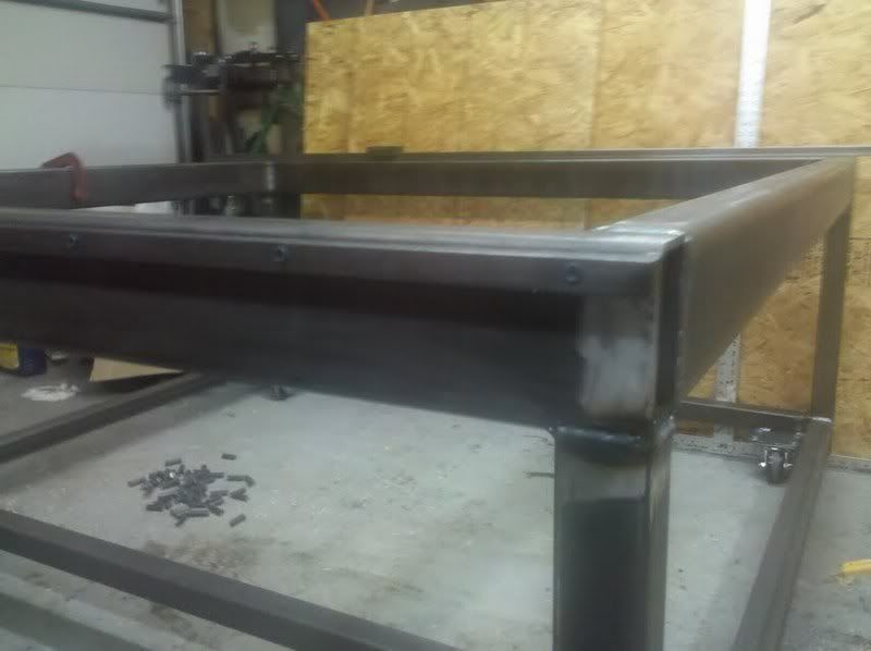
Next week the T-profile arrives for the gantry so I can put that together and get the other Linear rail install on the X-axis. These linear rails allow very very small amount of mis-alignment so I figure I would use the gantry as a alignment bar between the two to make sure they are parrallel. Basicly push the gantry to one far side to punch, drill and tap the one bolt then to the far side for the same and so on.
-
07-15-2011, 01:51 PM #4
Registered
- Join Date
- Jun 2011
- Posts
- 0
Hello Shefron. New to cnczone, been lurking for awhile. Seeing this build with all the great pictures, I had to come out of the lurk mode :-). I'm well below "newbe" when it comes to cnc so posts like yours helps alot. It will be awhile before I can start a build but your ideas are exactly what I am planning. Hope you don't mind me borrowing some of your ideas?
I might have missed it in your post but what thickness metal did you use for your frame?
Thanks for Sharing this build with all the helpful documentation. I look forward to seeing this build come together.
-
07-18-2011, 01:11 PM #5
Registered
- Join Date
- Oct 2010
- Posts
- 57
The frame was 2x4x.188(3/16) wall rect tubing. I dont mind posting the solidworks model when Im done which should be very close to correct dimensions when Im done. Issues like the gantry being 1/8inch off will be corrected in my 3d model for no other reason then to make it correct. Use any idea you would like since I did take some ideas from other people and builds to help construct mine. Originally Posted by plainsman

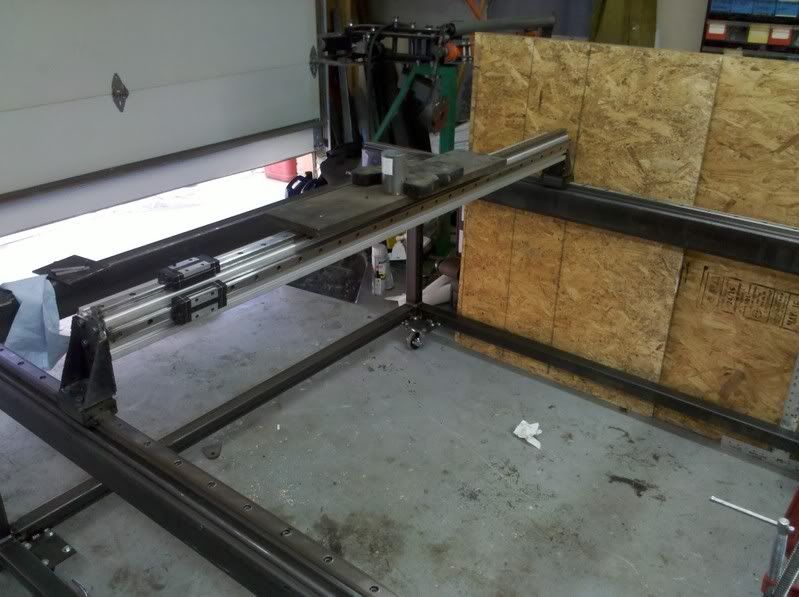
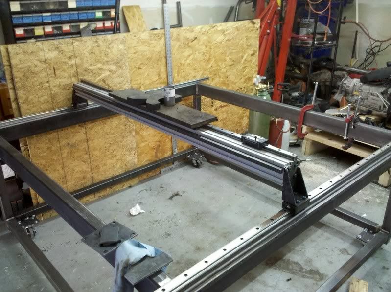
The gantry width is a 1/8inch off the compared to my 3d model due to me not leaving enough extra material on the T-profile when I did the rough cut. I did square each side up perfectly using a horizontal mill at the college which accounts for some of the error since I didn’t plan on squaring both sides but the setup was too easy to pass up. I used the standard procedure of using a jig or just the gantry assembled to make sure the linear rails were parallel and would not bind during movement. At first I was planning on installing a few bolts into the second rail to avoid binding issues but as more bolts were added I never noticed any binding issues so both linear rails are fully bolted down.
I was using some 2x4s and other spacers to hold the gantry up so I could remove the end mount for a little trimming using a grinder. To save some time during mockup I made it so I could remove the linear rails on the gantry without unbolting everything. At a later date I may hog the side mounts out of solid AL or steel depending on what I can find at the college if the current ones are too weak for routing. But for now the current ones will be cleaned up today or tomorrow for more of a professional look plus some more bracing on them.
The gantry moves flawlessly and very easy over the entire travel. I was curious to see how well the rails would move with additional weight far exceeding anything it would see and I was happy with the results. There was a very small difference in the effort required to move the gantry with and without the additional weight of 56 lbs added which did not include the weight of the 2 linear rails and gear rack.
I should be able to order the pulley drive units after Tuesday and I should win the floating Z-axis for cheap on ebay since K2cnc never sent me a paypal request.
-
07-21-2011, 04:30 AM #6
Registered
- Join Date
- Oct 2010
- Posts
- 57
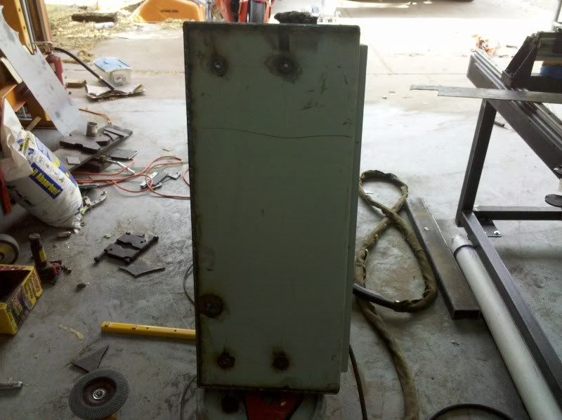
I found the new res for the water. I wanted the ability to drain the table unless I was using it which requires a air tight container to be able to transfer the fluid back up to the table. A salvage yard in ABQ gave me a cheap and easy way to do this. Shoot I only went there on a whim looking for a propane tank or transfer tank but this works out better.
Choice 1: Electrical Panel. I would say 10-12 gauge metal. $50
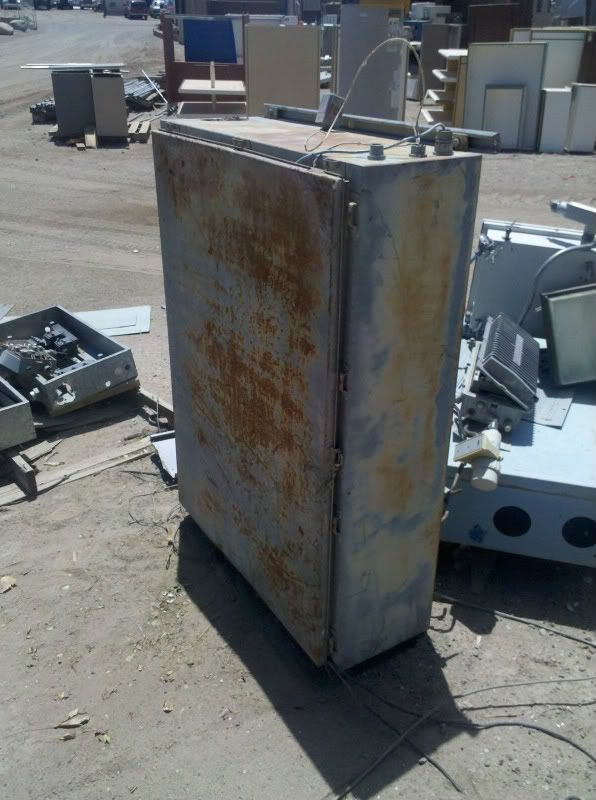
Choice 2: Another Electrical Panel. same thickness as the last. $75
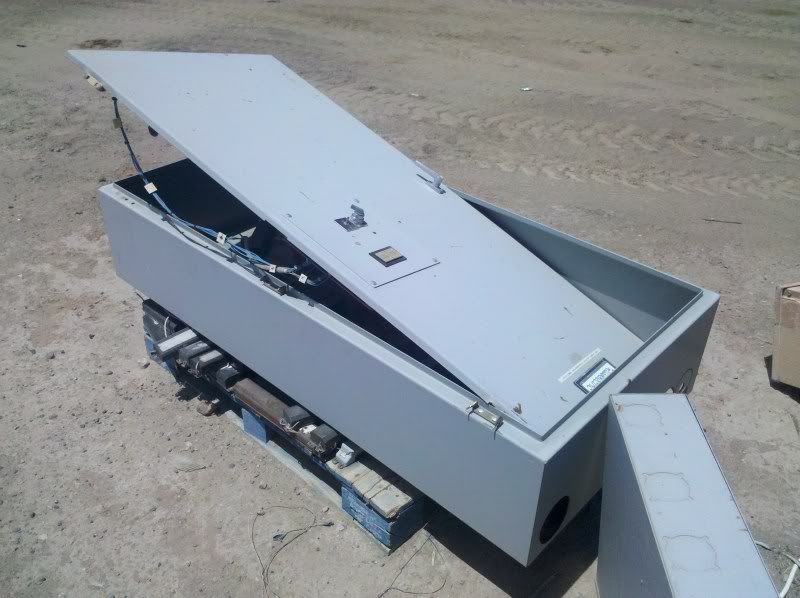
Short time later choice number 2 is at my house. The case seemed to be in better condition with no rust and holds 96 gallons vs 75 gallons like the first choice. My table at most needs 70 gallons but I figured there would be some unused fluid in the tank.
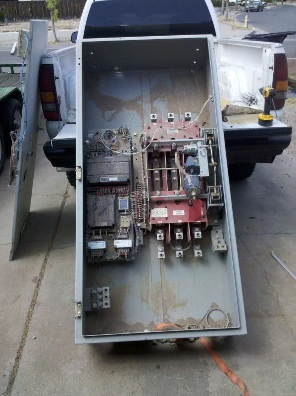
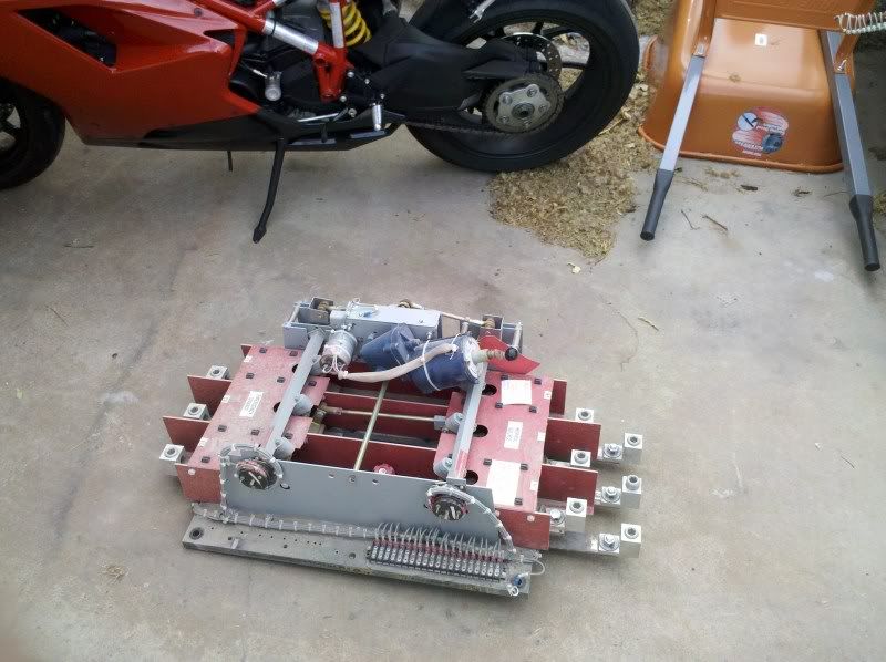
The freaking contactor was huge and works. Maybe this will go on the living room wall as a decorations.
**** ton of welding later to fill in the seams and block off the holes we have a container to hold water.
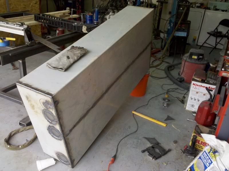
Test fitting the box under the table. Couldnt ask for a better fit.
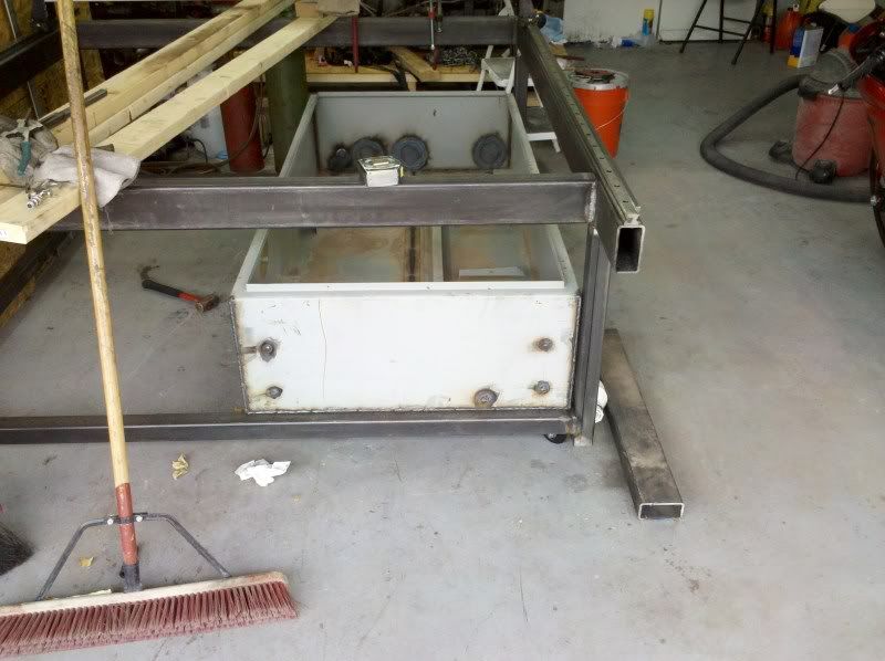
Leak test went pretty well. I had minor seeping but I expected that with mig welding and I couldnt always get perfectly clean welding. Debating on smearing JB weld on the leaks or caulking the whole box inside.
The only other decision on the res is wether to weld the top on or buy a seal for around the edges and clamping the thing down. I like the clamp idea if I need to clean the unit out or maintaince but I need to find some parts for it first.
Any thoughts?
-
07-26-2011, 06:04 AM #7
Registered
- Join Date
- Oct 2010
- Posts
- 57
I might just give that a try. Ill have to remember that when I can pressure test the water res. Originally Posted by CarterKaft
Here is a few updates
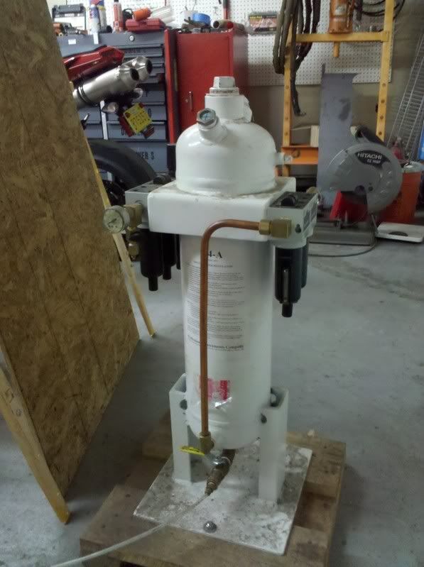
Got the water res welded up and the access door made. The door is maybe a little large but I will post pictures of that setup later this week. Got a freebie for the plasma air setup that I couldnt pass up. I will owe the person some plasma work later on but its worth it. Little big for mounting to the table so I will be mounting this on the main out from the air compressor after I install extra tubing to drop the temp going to the dryer unit.
Specs
•A pre-filter to remove large particles and droplets.
•A coalescing filter to remove almost all of the oil droplets and free water.
•A deliquescent dryer with a capacity of 15 standard cubic feet per minute (SCFM) at 150 psi.
•A regulator/filter downstream from the dryer and upstream from a carbon cartridge.
•An activated carbon cartridge to adsorb residual oil vapor and other organic contaminants such as tars and resins from cigarette smoke. THIS IS IMPORTANT. It is required even if an “oil-free” air compressor is used. The cartridge can be removed for periodic replacement.
•A final filter rated at 5 microns.
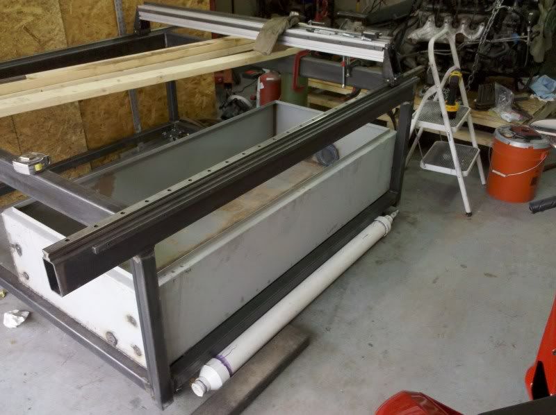
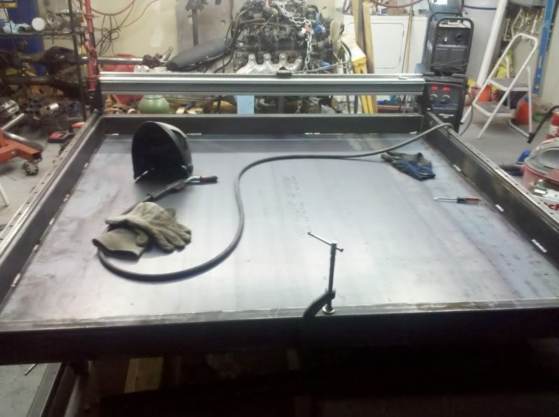
Most of the time I work byself as the previous pictures show which leads to creative ways of doing stuff. Here are the supports across the water table for the pan setup.
The sheet metal gave me a little bit of issue when ordering. Only one place in town carried a sheet that was wider than 5ft but when I arrived they were out of the smaller size of 6'x10'. The lady suggest I could come back with the trailer tomorrow for the sheet but I already took some time off work to make it before close so I ended up with a 6'x12' for a little more. I now know the next project once the table is done: Gantry crane. **** this **** was heavy at 315lbs total and I dont wanna imagine moving a 1/4 5'x5' sheet around by myself. Sheet metal place into the structure.
Stitch welded. Debating on using silcone to seal the rest with silcone or finish welding.
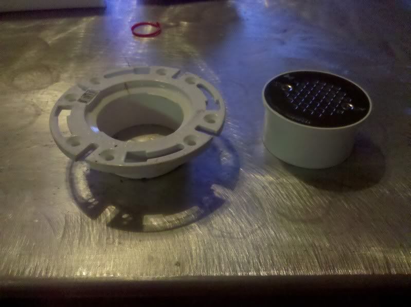
Here is the decided on method for bringing the water to the top. The flange fits a 3.5" I think thru it if I grind down the 2 nubs that stop the pipe. The top piece is a shower drain that fits a pipe also.
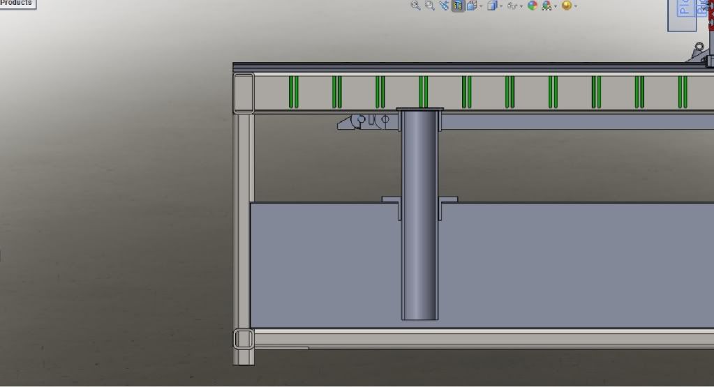
A quick rough cad of how the fill system will be layed out. The pipe will be about a inch off the bottom of the water res. Silcone will be the choice of sealant for this job to avoid making it permanent.
-
07-27-2011, 05:22 PM #8
Registered
- Join Date
- Jun 2009
- Posts
- 45
Hi Shefron,
This looks very promising.
I have two recommendations at this point:
provide for some shielding of at least the X-linear rails so the plasmadust and splatter wouldn’t foul your rails and bearings.
second: limit the air pressure on your watertank. I use a similar setup with the lid clamped on; when the air pressure is only a fraction to high the thing starts leaking (it usually stops leaking when the table is filled up and the pressure is down again).
One more thing: I wouldn’t feel safe about silicon to seal the watertable, if your slats will be placed in a curve they will give additional pressure on your welds and seal. In a large cutting job I had my water heated up to about 100 degr. F, not ideal for silicon sealant.
Arthur
-
07-31-2011, 05:26 AM #9
Registered
- Join Date
- Oct 2010
- Posts
- 57
125psi water test. 96 gallons went fast and the water at least cooled me down fast since it was 94 here. Originally Posted by Arthurmetal
[ame=http://www.youtube.com/watch?v=N0yCD1VQ3rQ]‪125psi full run.avi.wmv‬‏ - YouTube[/ame]
-
08-07-2011, 05:04 AM #10
Registered
- Join Date
- Aug 2005
- Posts
- 158
GE silicone sealant that you can get at most building centers is good to at least 400f. Would I use it on a plasma water table? No.... Originally Posted by Arthurmetal
-
08-07-2011, 09:39 AM #11
Registered
- Join Date
- Jun 2009
- Posts
- 45
One more reason I wouldn't use silicon sealants: when you are cleaning out the watertable from this thick mud of plasmadust which collects on the bottom of the table mixed with all sorts of cut-outs you will defenitly damage your seals.
-
08-30-2011, 01:15 AM #12
Registered
- Join Date
- Oct 2010
- Posts
- 57
Sorry about the slow updates. Life took a turn for the better the last few weeks. I have been putting out resumes since July to find a Mechanical Engineering job since I graduate in December. I do have a job at Lockheed Martin being a simulation tech but it was time to move on. About a month ago I got a phone interview at a solar plant for process engineer position. The next week I had a in person interview that lasted 3 hours for drilling part and 1.5 hours for the plant tour, which I also consider part of the interview. By the way, getting two business suits fitted to you is freaking expensive but it impressed the people alot that I went the extra mile. I always thought a suit was the minimal dress code for a engineering interview. Long story short I start on Sept 6 as a Asc Engineering till I finish my degree then according to my offer letter I will be promoted to Engineer but until then Im hourly working 50 hours a week with 10 hours being overtime.
Plasma details.
My PC sucks that I had for the table. Could barely run a web browser or even mach3 then take into account it is about 50-100 dollars for a decent video card for the system so I went a different route.
Old pc stats
AMD 1800+ XP processor
768 megs ram
on board video
New PC for table. Bought off ebay for $110 shipped to my door. Should arrive on friday.
Dell precission 670
dual Xeon 3.4 Ghz procs
2 gig ram
Nvidia Quadro FX3400 Video Card 256 megs ram
80 gig hard drive
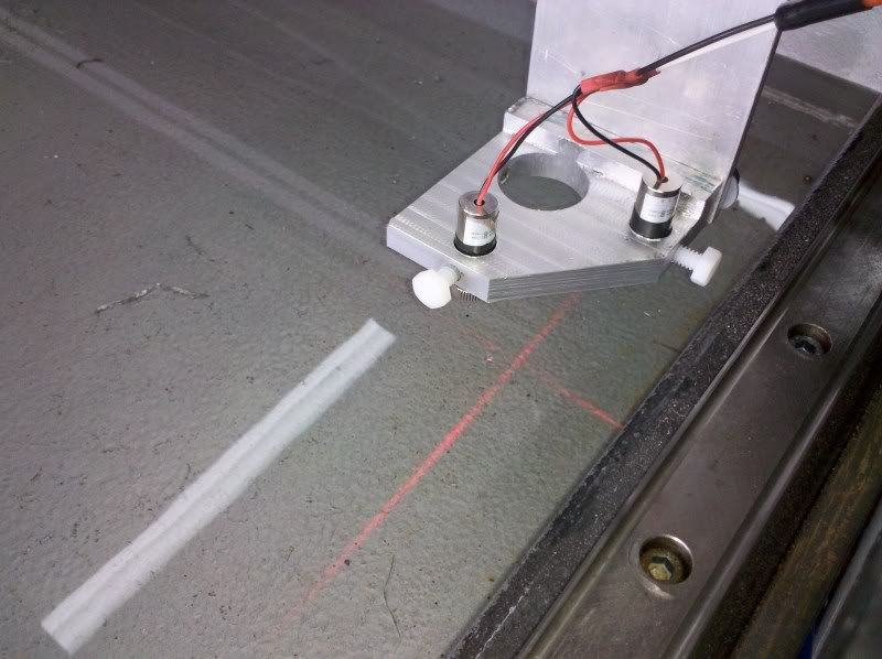
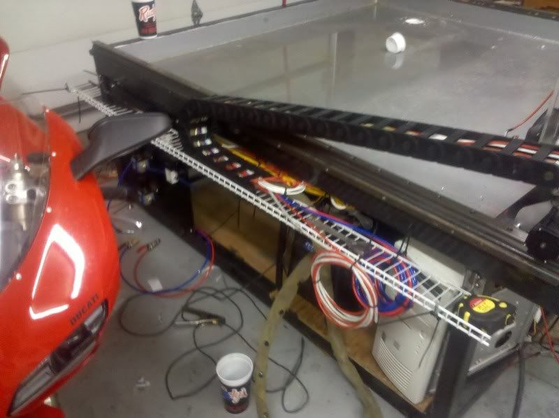
Installed the lasers for the torch alignment. I guess the chinese decided to make the case positive vesus the common practice of it being grounded. I drilled the holes one size bigger than wrapped electrical tape around the units and used plasic set screws to avoid shorting the system out.
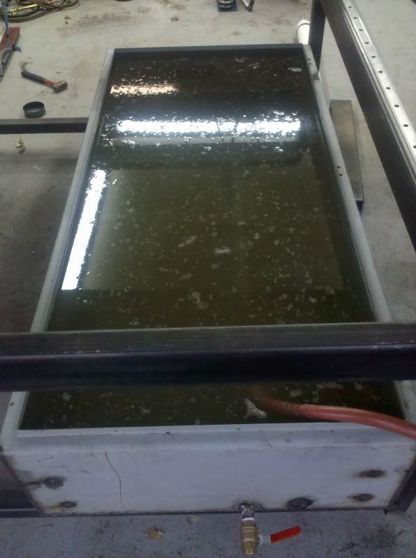
Next pet peeve. I could never tell how full the water tank was so I added a simple sight tube to it.
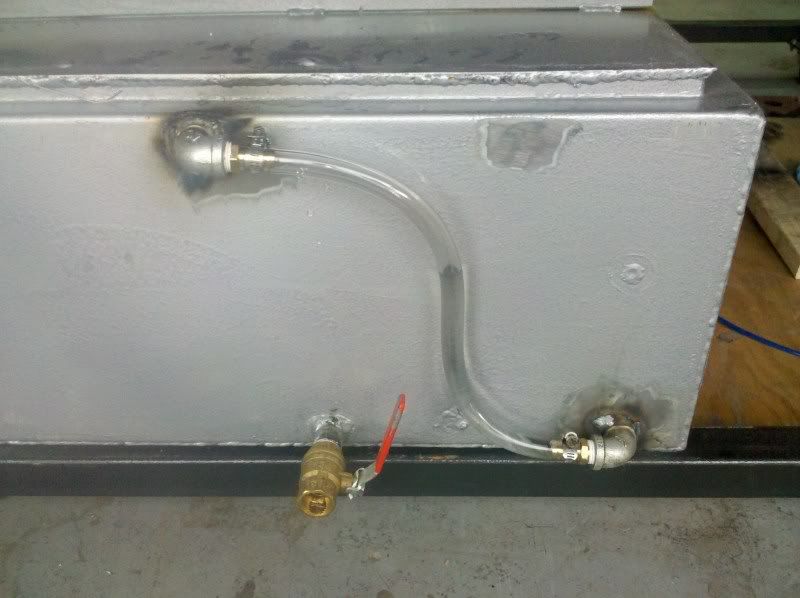
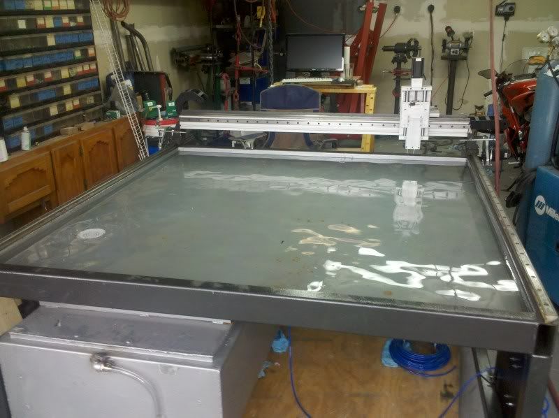
Table full of water. Takes about 4 hours for the water level to drop 1 inch which I figured would happen since the tank has a few very small air leaks. I can live with this issue perfectly fine.
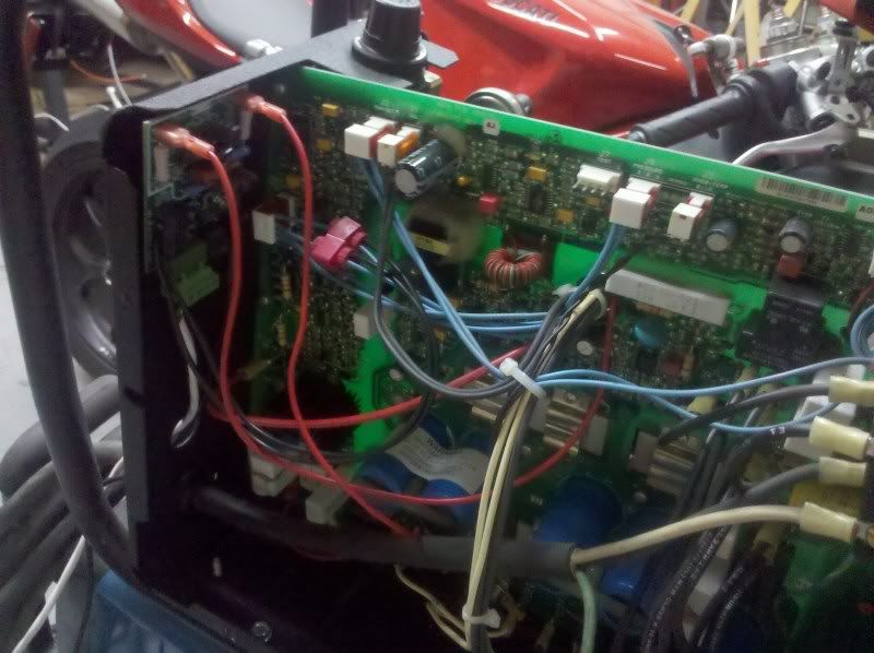
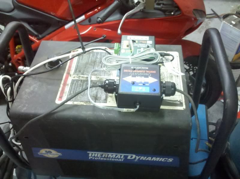
Cutmaster 38 wiring was a little interesting since nobody posts info about turning this unit into a cnc one. The unit does not have a ARC ok output so a Digital Current Probe was needed from CandCNC.
-
08-30-2011, 01:16 AM #13
Registered
- Join Date
- Oct 2010
- Posts
- 57
Both cable trays are mounted on the table.
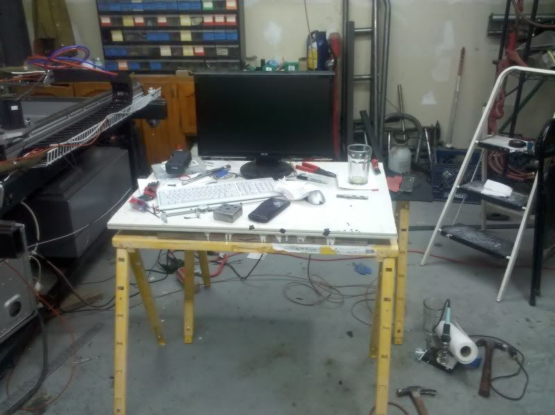
My temp computer desk / workbench next to the table. What a difficult design the table was to make.
Now onto the issues and word of caution for other table builders.
Install hard stops into your table. Until a lady friend comes over tonight, the gantry will be staying where I lifted it back onto the table since its too heavy for me to set on the precision rails alone and get carriages lined up.
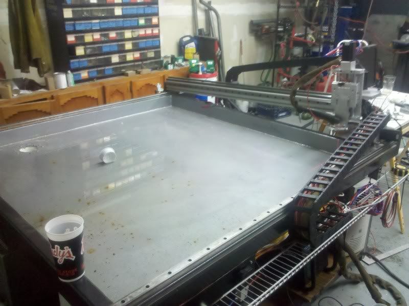
A gantry that weighs about 80-90lbs that is travelling at 750 Ipm does not feel good when it comes flying off the table due to a idiot using command line code.
G0 X-3 does not mean go back 3 inches. Oh no it means go to -3 reference.
Other issues Im having. For some reason the steps for the X-rail are not coming out like the calculation say they should. Running a alignment from Mach3 I get steps of 1739 per inch. Using a tape measure when traveling the length of the machine, it appears to be accurate.
Now the math part according to CandCNC manual and other posts. System uses 3:1 drives from cncrouterparts.com
(200 micro stepping)* 10 (gecko 540)= 2000
(2000/pi)*3 = 1909.824 steps and is the same number on cncrouterparts.
When using the 1909.824 the travel is off on the X-axis. Any ideas why?
-
08-30-2011, 06:21 AM #14
Registered
- Join Date
- Feb 2009
- Posts
- 227
Is the drive system exactly the same as the Y axis?? How far is it off?? I like your build you are very close... Just keep working at it your almost there... You shall see sparks in no time... Originally Posted by Shefron
BTW where did u pick up your laser guides at... part number please im going to order some of those...
-
12-17-2011, 12:13 PM #15
Registered
- Join Date
- Jul 2011
- Posts
- 29
can I ask a real newb question? Originally Posted by Shefron
why do you have to pressurize the water tank? is the water circulating from the tank to the table?
I'm looking into buying a cnc plasma table it is used and I can not find any info on it at all, I'm here digging or any info I can find
thank!
I
-
12-17-2011, 07:10 PM #16
Registered
- Join Date
- Aug 2005
- Posts
- 158
Instead of using a pump, compressed air is used to push the water back up to the table. When you want to get small parts that fall through the slats etc, you dump the water to the lower holding tank.
Take a look at these vids i found
[ame=http://www.youtube.com/watch?v=0wZXw4Ucl14&feature=mfu_in_order&list=UL]Water table Filling up - YouTube[/ame]
[ame=http://www.youtube.com/watch?v=Zxrd4UgvZhA&feature=related]Water table Fill & Drain - YouTube[/ame]
-
12-18-2011, 03:26 PM #17
Registered
- Join Date
- Dec 2008
- Posts
- 41
Very impressive build. I really like the lazer finders, post up some details on those. One little tip I think you need to do for safety, remove the gas cans from the welding shop! (pics in posts 1,5, &6)
-
12-18-2011, 06:48 PM #18
Registered
- Join Date
- Oct 2010
- Posts
- 57
Thanks. The lasers are somewhat crap since they came from china and the case is positive instead of negative like everything else. So they have to be isolated from the table or sparks happen. The gas cans have been moved for some time. Did I post a link where I got the lasers? Originally Posted by Rhinorider
Im finally done with college. I'm proof pigs can fly and hell has frozen over. I'm now officially a Mechanical Engineer with a degree. Only took 7 years for the events to happen.
-
12-19-2011, 03:26 AM #19
Registered
- Join Date
- Dec 2008
- Posts
- 41
Congrats on obtaining your degree. Took me until I was 46 to get mine. I like the idea of the lasers, when I build my table I'll look into incorporating those, maybe find some better lasers with negative case. I didn't see where you posted the link where you got yours. Glad you moved those cans. I work for the government as a safety inspector, it is just natural I pick up on those things. Again really nice build.

 Reply With Quote
Similar Threads
-
Precision Plasma LLC 2' x 3' DIY Plasma Table
By rchacich in forum News AnnouncementsReplies: 9Last Post: 08-26-2011, 12:05 AM -
My first cnc: plasma table 3.5' x 2.3'
By balestraio in forum Plasma, EDM / Other similar machine Project LogReplies: 17Last Post: 06-20-2011, 08:38 AM -
Precision Plasma LLC 5' x 5' CNC Plasma Table
By rchacich in forum News AnnouncementsReplies: 0Last Post: 11-10-2009, 05:08 PM -
CNC Plasma Table - TPI
By Degrom in forum Waterjet General TopicsReplies: 7Last Post: 11-14-2007, 08:52 PM -
Looking to buy a NEW Cnc plasma table
By Perp in forum Waterjet General TopicsReplies: 13Last Post: 09-21-2006, 04:50 PM
