


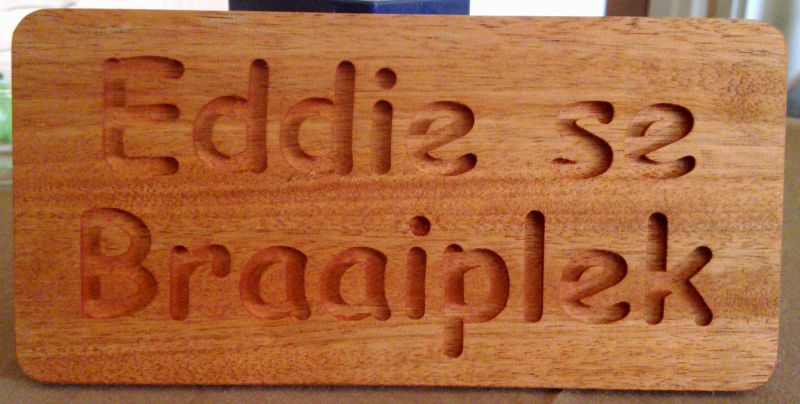
Here is the final result after oiling and finishing
Thread: Tonsen - eBay ReadyToRun Mill
Results 201 to 220 of 276
-
11-14-2010, 09:13 AM #201
 Registered
- Join Date
- Sep 2010
- Posts
- 0
create g-code once, cut forever!
-
11-14-2010, 11:09 AM #202
Registered
- Join Date
- May 2010
- Posts
- 0
further testing: linearity
[QUOTE=johnnytaaikop;849896]Here is the final result after oiling and finishing
 [QUOTE]
You look quite satisfied with the new machine. No problems so far?
To all: what are you using for oiling/greasing the ballscrews and rails?
To RomanLini: you are right to point out that the backlash test was not fully "by the rules", I corrected that and will re-cut one of these days. dxf file attached.
indeed, this left me investigating further reasons for non-linear behaviour of the y axis, I cut a series of equal squares at 10 cm intervals on the z axis, here are the results. Previously established backlash correction is on. 1.5 mm diameter spiral cutter (actually it does not measure _exactly_ 1.5 mm, a bit more), 7 passes on 6.7 mm plywood. Each block is measured twice:
In summary, a variation of 150 microns along the y axis. It *might* be possible to input software correction parameters in emc. Going to try one of these days.Code:20101107 test linearity bloc 1 measure1 measure2 average y 29.76 29.74 29.75 x 29.79 29.79 29.79 bloc 2 (y +10cm) measure1 measure2 average y 29.88 29.89 29.885 x 29.88 29.90 29.89 bloc 3 (y + 20 cm) measure1 measure2 average y 29.92 29.95 29.935 x 29.81 29.79 29.80 bloc 4 (y + 40 cm) measure1 measure2 average y 29.91 29.89 29.90 x 29.81 29.78 29.795
It seems to me this is coherent with the expected performance of C7 ballscrews and there is some discussion in the sheer mass of cnczone...
http://www.cnczone.com/forums/linear...c_pcb_not.html
Does it seem excessive? What results are you guys getting?
L.
Last minute note: vibration is not the same at different points in the bed, so it might also be playing some role...
-
11-14-2010, 12:00 PM #203
Registered
- Join Date
- Oct 2005
- Posts
- 2392
I'm just going to take a guess but I think modern rolled ballscrews are more linear than that. Mine are NSK ballscrews BS1208A8 (only cheap screws) and are very linear, the biggest errors I get are from thermal expansion and that is along the length of the screw as you would expect.
If both your ballscrews are the same size they were probably cut from the same stock or at least from long stock. And they should be similar linearity.
I would investigate the possibility that there is some binding (or flex) of your Y axis, maybe both. You could check if it turns and slides smoothly, or maybe loosen something so it does slide very easily then take some more light test cuts. Maybe try some super-lube on the Y rails and nut like a silicone spray?
-
11-14-2010, 01:26 PM #204
Registered
- Join Date
- May 2010
- Posts
- 0
Haven't tested the x axis yet, since it is the y axis that worried me. Lubrication is a preoccupation indeed, shame on me because when I started using the machine I didn't have a proper greasing press. Have got one since then. Originally Posted by RomanLini

The x and y ballscrews are identical indeed, 16 mm diameter and 5 mm per turn, there is one obvious difference: the ballnut. The y (long) axis ballnut is bigger, closed design and features a standard greasing port. The x (short) axis ballnut is smaller and does not have a greasing port. No data on their specific features (we users should try to find out).
From what we can find here Ball Screw Accuracy Design with C7 rolled ballscrews we should expect an upper variation limit of + or - 50 microns per 300 mm, so with an y axis about 600 mm long, we should expect a maximum variation of + or - 100 microns.
Is that relevant? probably not, if I am cutting a 500x300 mm plywood enclosure or a smallish wooden part for a robot. Probably not relevant also for milling a 100x100 mm PCB. Will be testing that soon.
NSK stuff is apparently well known for much tighter tolerances. Also, ground ballscrews (as opposed to rolled ones) are supposed to have more precision.
But the price goes high fast. I wonder if those "used NSK linear axis" offers are worth of interest: what is the loss of precision imputable to wear? - since I'm meditating about CNC II which would probably be a self-built 200X200 or 300x300, moving table, mixed epoxy-granite-plywood. Again, prices increase swiftly for quality parts.
L.
-
11-14-2010, 01:33 PM #205
Registered
- Join Date
- Oct 2009
- Posts
- 20
what is a greasing press? Originally Posted by Lanthan
and what all should i lubricate and with what? (oil? vaseline?)
-
11-14-2010, 01:35 PM #206
Registered
- Join Date
- Oct 2009
- Posts
- 20
nice Originally Posted by johnnytaaikop
what's the wood type?
and what bit and settings (feed rate, cut depth) did you use?
-
11-14-2010, 04:01 PM #207
Registered
- Join Date
- Sep 2010
- Posts
- 0
Lanthan: yes, at this stage I am happy with the machine and have had no problems.
Sman!
The wood I believe is okoume.
3mm endmill,3fl 9000RPM, 0.75mm deep cuts at 5mm per sec.
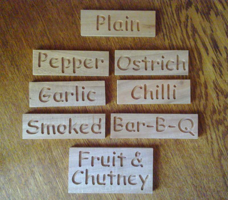
Here are some more signs made this morning for a friend's deli:
 create g-code once, cut forever!
-
11-15-2010, 06:33 AM #208
Registered
- Join Date
- Oct 2005
- Posts
- 2392
I'm not sure you are reading that right. The overall error (what they call; "E mean travel deviation") should be dialed in with one axis caibration value in your software. And that is temperature sensitive so you calibrate that at your most typical operating temperature, ie with the leadscrew at its typical operating temp. Originally Posted by Lanthan
So to test and fix that you cut some test cuts in a way that eliminates backlash and tool size and compare the measurement. So if a 100mm test cut measures 101mm and a 500mm test cut measures 505mm you know how much to change your calibration value.
What your tests showed with the variation on each small 30mm piece is shown in that chart as; "e travel variations". This is the individual variation at any *point* on the screw, which should be < +/-50 on your C7 screw.
In reality your machine travel variation error (non-linearity error) will be much less than that, as your leadnuts don't connect to a single point on the screw, but to many points over 20mm or more screw length (where all the balls engage). So that averages the variation errors. Probably to half, maybe much less depending on the design of your antibacklash system. So that error should be < +/-20 or so.
Your test blocks range in size from 29.750 to 29.935 which is an overall error of 0.185 or +/- 0.092 which is MUCH larger than I would expect from "individual variations" error in the leadscrew.
I still think it is caused mainly from binding and or flex in your Y axis.
Nice signs Johnnytaaikop! Looks like a very nice clean cut edge. Did you think about putting some dark coloured paint or epoxy in the text recess?
-
11-15-2010, 06:57 AM #209
Registered
- Join Date
- Sep 2010
- Posts
- 0
Thanks! Originally Posted by RomanLini
My friend still has to do painting/staining of the wood.
I just cut it and sanded it a little.
The rest is up to him
create g-code once, cut forever!
-
11-15-2010, 07:09 AM #210
Gold Member
- Join Date
- Feb 2006
- Posts
- 7063
No, that's not correct. The linearity error, or lead error, is specified as the maximum deviation from ideal position you'll see over some specified length of screw. For rolled screws, it's typically +/-0.003"/foot. This means that for any one foot length of screw, you may see one or more points that deviate from the ideal position by as much as +0.003", and one or more other points that deviate from the ideal position by as much as -0.003". So, the distance between those two points may be off by as much as +/-0.006". Originally Posted by RomanLini
Last I knew, Roton rolled screws were among the least accurate, spec'ed at +/-0.004"/foot maximum error. Of course, most ballscrews will be better than the spec, but there are no guarantees. Nook XPR rolled screws are spec'ed at +/-0.001"/foot, almost as good as ground screws, which are typically +/-0.0005"/foot.
The length of the ballnut, or the number of ballnuts, does nothing whatsoever to reduce lead error.
The only way to correct this error is to use "screw mapping" - a correction applied by the CNC controller based on the current position of the nut on the screw, which moves the machine to the correct position, despite the screw error. Mach3 supports this, though I don't believe it works correctly. I have no idea whether EMC supports it or not, but I'd guess it does. But, generating the screw mapping correction data requires having a very accurate DRO on the machine, so you can measure the actual lead error at many points along the length of the screw, and that DRO will likely cost as much as higher quality screws. And, few hobby projects really require such high accuracy anyway.
Regards,
Ray L.
-
11-15-2010, 07:44 AM #211
Registered
- Join Date
- Sep 2010
- Posts
- 0
Talk about splitting hairs...!
create g-code once, cut forever!
-
11-16-2010, 10:44 AM #212
Registered
- Join Date
- Oct 2005
- Posts
- 2392
Hehe I can understand discussion of errors less then 0.001" being described as splitting hairs.

But I'm very interested in HimyKabibble's expertise on this. Although HK, I'm still not sure if you are talking about the linear lead error (shown as 'E' in the link above) that is measured per foot and depends on temperature etc or the non-linear +/- error at any particular *point* on the screw (shown as 'e' in the link above).
Lanthan should be able to compensate the linear lead error in software with a single value. And after that the +/- error at any particular point should be pretty small seeing as it's averaged over all the contact points of his ballnuts and on an anti-backlash ballnut that can be over 2" total length of screw.
On my machine with the cheap-ish NSK rolled screws I can cut small parts anywhere on the table and be within 0.001" size of each other. Part of that accuracy I chalk up to having tight plastic leadnuts 30mm long that average point errors over 30mm of screw.
What Lanthan describes above is cutting 30mm pieces at different places on his table and they vary in size from 29.750 to 29.935 which (to me!) sounds MUCH greater error than what should be attributable to his C7 screws alone.
-
11-16-2010, 07:19 PM #213
Registered
- Join Date
- Nov 2007
- Posts
- 72
Nice, and more pictures are welcome.
-
11-23-2010, 08:38 PM #214
Registered
- Join Date
- May 2010
- Posts
- 0
mo'pics
Meanwhile... Originally Posted by FunnyNYPD
I've routerized a servo gripper on thingiverse
. Dxf files and another picture there.
Thx for the insights on ballscrew precision. Yes, emc allows for correction of linear error as well as parameters for the ballscrews, but as mentioned, without an (expensive) DRO I'm sort of stuck. I guess it is not really the main priority at this point...
Cheers, L.
-
11-24-2010, 06:10 AM #215
Registered
- Join Date
- Sep 2010
- Posts
- 0
How about a video of the gripper in action?
create g-code once, cut forever!
-
11-28-2010, 06:42 AM #216
Registered
- Join Date
- Sep 2010
- Posts
- 0
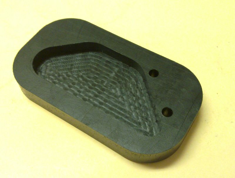
Yes, it cits aluminium...
I did a test cut for proof of concept on 6.5mm thick aluminium. The slot I cut is 20mm x 6mm and 6.5mm deep. I was conservative and made 0.2mm deep passes at 3mm per second feedrate. It cuts well at 9K rpm. Takes a long time to cut though. I used a 3mm, 3fl carbide endmill, no lube and constant vacuum-cleaning to remove chips and cool the workpiece. Second pic shows inside finish of the slot; it looks better in real life.
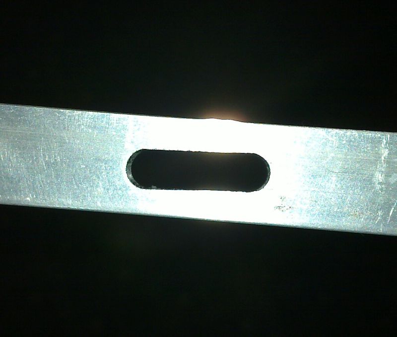
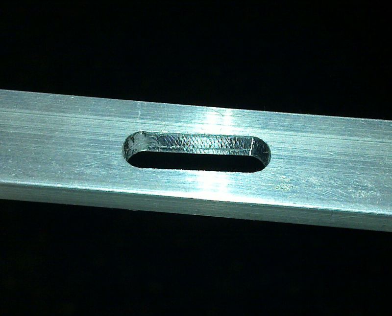
Any thoughts?create g-code once, cut forever!
-
11-28-2010, 12:36 PM #217
Registered
- Join Date
- Oct 2005
- Posts
- 2392
Cool gripper Lanthan! It would look awesome in clear acrylic.
Johnnytaaikop that extruded aluminium is horrible stuff to cut! You should get better results with all the same settings and just going to a better aluminium grade like 6061.
Otherwise try a couple of drops of oil, you can apply to the job with a artists paintbrush or on the end of a plastic skewer (something that won't destroy your tool or job if it gets too close). I've got an old empty can of spraylube and its tube that is good because it just dribbles a couple of drops instead of plastering my whole machine with lube.
I'm no expert on feedrates but with a light cut like 0.2mm you can probably bump that feedrate up, maybe double it. It probably depends more on what your machine can take force wise than on the "correct" feedrate.
-
11-29-2010, 08:59 AM #218
Registered
- Join Date
- Sep 2010
- Posts
- 0
I cut some plastic this morning with good results:
3mm bit, 3fl, 7mmper second feedrate, 1mm per pass.
The workpiece is a "bigfoot" for my motorcycle sidestand.
 create g-code once, cut forever!
-
12-01-2010, 06:38 AM #219
Registered
- Join Date
- Sep 2010
- Posts
- 0
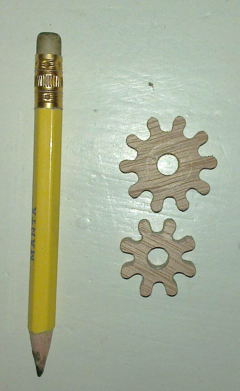
Some small gears I cut from plywood for a clock project some time in the future.
Centre hole is 6mm.
 create g-code once, cut forever!
-
12-05-2010, 01:13 AM #220
Registered
- Join Date
- May 2010
- Posts
- 0
Griped gripper
Would love to, but actually (as expected) the original gears gave me a lot of grief. After I broke a second sh**** micro-servo I re-designed part of the wrist with better tolerances and a couple of involuted gears (Toolpath: Inkscape's gear plugin, offset adding the tool radius in points using tutorial at cncclub.ru, export to ps, use ps2edit -f dxf_s, rescale x25.4, add the rest). Originally Posted by johnnytaaikop
Much smoother now! The new dxfs are here: Mini servo gripper, improved gears by Lanthan - Thingiverse. Still waiting for a pack of servos (building the rest of the arm). Will post pics. Then I foresee cutting a servo shield to control this with an arduino.
Otherwise I'll be trying this tomorrow:
Just an h-bridge with a couple of TIP120 and TIP125. Learning to use gEDA, so it might not be the most elegant or compact board.
Cheers,
L.
PS: RomanLini: I love plywood, it is rock-bottom cheap, easy to cut and looks... well, like punk***. ;-)
***Or "intermediate technology"...

 Reply With Quote
Similar Threads
-
TONSEN TS3040C-H80 breakout board
By ZZRBlokey in forum Chinese MachinesReplies: 8Last Post: 11-15-2014, 08:10 PM -
Tonsen TS3040C-H80 - replace spindle directly on Z axis?
By bearer in forum Chinese MachinesReplies: 10Last Post: 04-28-2013, 10:21 AM -
Ebay mill to CNC
By nate4567 in forum Maintenance DIY DiscussionReplies: 0Last Post: 06-17-2011, 02:19 AM -
Maho mill on ebay
By yoopertool in forum Deckel, Maho, Aciera, Abene MillsReplies: 0Last Post: 08-16-2007, 03:14 AM
