


So i found the schematics ect, and have been playing with arduino last couple weeks anyone want to work together to build one off his design?
Results 21 to 40 of 250
-
01-20-2013, 09:38 AM #21
 Registered
- Join Date
- Aug 2006
- Posts
- 157
-
01-20-2013, 07:13 PM #22
Registered
- Join Date
- Aug 2006
- Posts
- 157
So still looking at things, I have an arduino UNO and i am building a list for the things needed to replicate this. I found the files and started to try to understand things first.
I am not a great electronics guy but leraning the best i can, I got a Ardunio UNO board a few weeks ago and learned the lcd programming ect. It would appear to me that this could be built for around 30 bucks if u actually took the chip off the board. I almost hit the buy button on a superpid last week and i am kinda looking forward toa project. But of course buying a proven, highly acclaimed product like a superpid would be more beneficial. But then again i built my cnc out of roller blade bearing and bike chain. So perhaps a DIY router congrol should eb attempted. I will get a parts list done tongight from what i see on the youtube videos and the files.
Hoping someone will jump on board wiht me . But if not i will document the best i can
Tim
-
01-20-2013, 07:18 PM #23
Registered
- Join Date
- Dec 2010
- Posts
- 0
Hello Tim
not sure how much I can contribute, but happy to ride along
I have quite a bit of 'duino experience, but not mush with the PID algorithm
I get the theory, but have yet to build a working example
until now maybe!
cheers
Mike
-
01-20-2013, 10:05 PM #24
Registered
- Join Date
- Aug 2006
- Posts
- 157
great mike, well i am new to arduino, i code mostly in c# and thats all self taught, so perhaps we can work off eachother. It appears he posted the arduino code. so the main thing would be just building the pcb.
I plan for now to use 1/16 plexiglass with drilled holes on my cnc then connet the backside with wire. Since this si my first circuit other then test ones thats my route for now.
I am now getting my printer situated so i can print all the documentation he posted earlier. All the credit goes to the guy who started this thread. I have to relook at the name to thank him correctly.
I will get a parts list and how i beleive the circuit works although i am not an electronics expert but hopefully together we can put a good DIY on here for others to learn.
Tim
-
01-20-2013, 10:10 PM #25
Registered
- Join Date
- Aug 2006
- Posts
- 157
Also as a sidenote my plan is to try to get this to work and if it does then also make a dual,
same board will do my speed controls, and also do my extruder heating and heatbed control.
i have really been wanting to do a head for 3d printing on my machine. but theat the next step
-
01-20-2013, 10:21 PM #26
Registered
- Join Date
- Aug 2006
- Posts
- 157
i uploaded the daigrams i found, again thanks goes to the original thread starter. I assume that in the diagram a 390 saying R14 is a 390 ohm resistor. I am building a parts list now
-
01-20-2013, 10:33 PM #27
Registered
- Join Date
- Aug 2006
- Posts
- 157
2W01G 2 amp bridge rectifier .52 from digikey
Red led
green led
2x 4.7k ohn resistor
1.2k ohm resitor
15k ohm resistor
2x 390 ohm resistor
100 ohm resistor
2x 22k ohm resistor
470 ohm resistor
39 ohm resistor
PC817 photocoupler .52 digikey (few to choose from have to look)
MOC3021 TRIAC .76 digikey
TR Bt139x TRIAC 1.76 digikey (different models need to discuss)
Capacitors______________________
2x 47u
.22uf
-
01-20-2013, 10:54 PM #28
Registered
- Join Date
- Dec 2010
- Posts
- 0
which circuit diagram are you going with?
-
01-20-2013, 10:54 PM #29
Registered
- Join Date
- Aug 2006
- Posts
- 157
Straga, Originally Posted by straga

Я надеюсь, что вы можете помочь нам дальше с проектом. Я уверен, что с языковым барьером трудно помочь иногда. Я ценю вас этот обмен с сообществом ЧПУ. Я надеюсь, что если мы столкнуться с проблемами, вы будете так любезны помочь. еще раз спасибо
Тим
-
01-20-2013, 10:55 PM #30
Registered
- Join Date
- Aug 2006
- Posts
- 157
i am thinking the one he had that was not under "old" Originally Posted by mmcp42
I am curious do you use skype? it be great to be able to free chat some while working on the concept my skype is timmyb46 for anyone interested
-
01-20-2013, 11:00 PM #31
Registered
- Join Date
- Aug 2006
- Posts
- 157

-
01-20-2013, 11:06 PM #32
Registered
- Join Date
- Aug 2006
- Posts
- 157

-
01-20-2013, 11:25 PM #33
Registered
- Join Date
- Aug 2006
- Posts
- 157
I just started hacking apart random electronis around my basement that i have been thinking of taking to the dump. found an ancient pc gonna see what peices i can find in there. This might turn into quite the fun project
-
01-20-2013, 11:44 PM #34
Registered
- Join Date
- Dec 2010
- Posts
- 0
I just found the same circuit!
just converting it to EAGLE so we can do something useful with it
-
01-21-2013, 12:03 AM #35
Registered
- Join Date
- Aug 2006
- Posts
- 157
sweet i know eagle is apparently the pcb software. rememebr i am new to this. I am running to radioshack to see what parts they may or may not have there. I got a protosheild in my arduino on top and am starting to layout the stuff
Again in case u missed it above i am on skype if at some point u want to type back and forth live. I am trying to understand the two different kinds of triacs used. where did u find the schematic? is it a different site? for now i am just gonna breadboard it up then solder i beleive. let me know what your plan is. we can work together going forward.
-
01-21-2013, 12:06 AM #36
Registered
- Join Date
- Aug 2006
- Posts
- 157
i also see he used a pickup with a magnet for rpm. I am thinking a IR diode version if u know what i mean
-
01-21-2013, 12:10 AM #37
Registered
- Join Date
- Dec 2010
- Posts
- 0
I got the schematic from the githup zip files, same one as you posted the picture for
still working on the triacs - not sure why there's two!
one ought to be enough
I am expecting to use an IR LED/sensor for the speed pickup
-
01-21-2013, 12:15 AM #38
Registered
- Join Date
- Aug 2006
- Posts
- 157
GREAT!!! that was my plan also. Im heading to the shack although i doubt they will have anything. The specs from digikey looked the same to me on the triacs. Maybe he used what he could find around his place. I will be back later. I work this week so was hoping to get some progress done tonight enought to keep me excited lol
see ya in a bit
-
01-21-2013, 12:28 AM #39
Registered
- Join Date
- Dec 2010
- Posts
- 0
I have the code open in one hand and schematic in the other
helps to know what the code is trying to do with the hardware and vice versa!
I think we can swap hall effect and IR quite easily as long as we get a solid signal from either
looking at the circuit again I think there's only one triac U12
U41 is an opto isolator - part of the zero crossing detection using a 12 volt signal derived from the mains supply
U11 is another opto-isolator to drive the triac
hope that all makes sense
good shopping
cheers
Mike
-
01-21-2013, 01:41 AM #40
Registered
- Join Date
- Aug 2006
- Posts
- 157
Ok I got all resistors. I have to learn more about the triac. I will post my concept of what's going on later. I could not find the opto. Or the right bridge rectifier at RadioShack. I'm gonna order tomorrow the rest. If u think I shld order anything different let me know. I'm kinda. Electronics newb so hope I don't hinder u to much mike. Hoping to be using it by this weekend.
Thanks
Tim

 Reply With Quote
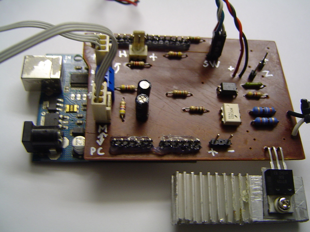
Similar Threads
-
CNC Controller with Arduino - open source
By Christian Knüll in forum Open Source Controller BoardsReplies: 16Last Post: 12-22-2012, 10:46 AM -
Arduino PID Motor speed control for router
By EL34 in forum CNC Machine Related ElectronicsReplies: 16Last Post: 12-02-2012, 11:34 PM -
Open Source Spindle Control
By rcpilot82 in forum Open Source Controller BoardsReplies: 7Last Post: 05-27-2011, 10:25 PM -
EMC2 (Open Source) Plasma Control w. THC
By rugludallur in forum Waterjet General TopicsReplies: 0Last Post: 07-19-2006, 09:25 PM -
Any open source or cheap driver for bipolar motor 6 Amp, 2.7V??
By berryCR in forum Stepper Motors / DrivesReplies: 1Last Post: 06-10-2006, 05:43 AM
