


Great detailed drawings looks like you are a man after my own heart, design around what you have available I love to use up what I have or can get at the right price to make the best I can.
Thread: Thor
Results 21 to 40 of 83
Hybrid View
-
04-25-2016, 04:48 PM #1
 Registered
- Join Date
- Feb 2016
- Posts
- 381
Re: Thor
-
05-23-2016, 08:41 AM #2
Registered
- Join Date
- May 2013
- Posts
- 70
Re: Thor
Ive made some parts for the mill as well as start on the moulds. The moulds arent nearly ready yet, Ill take some pics when they are.
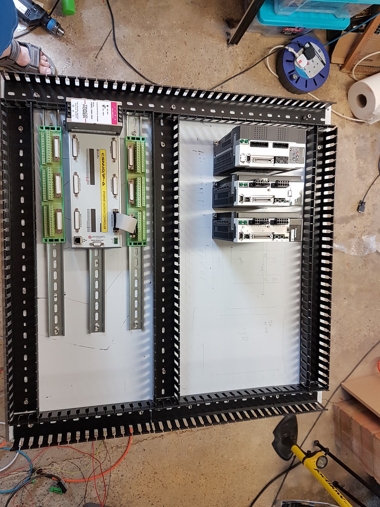
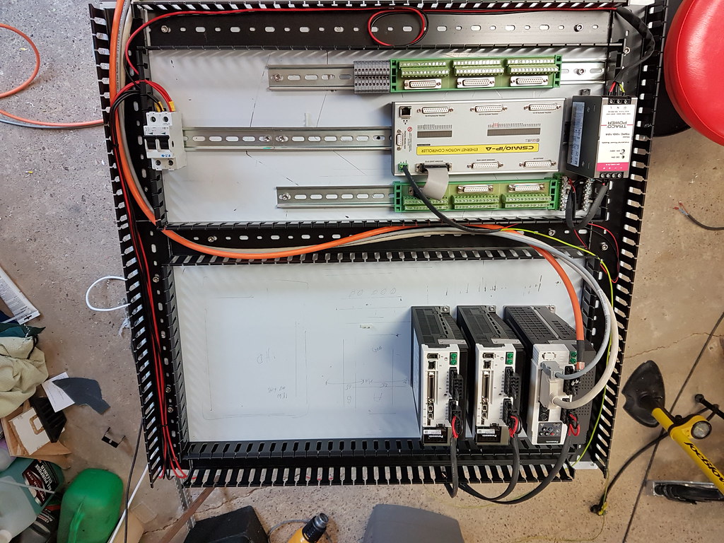
Started with the layout of the electrics yesterday as I now have space since completing another retrofit on a very nice small Concept machine.
Ill mount onto a stainless plate most likely, this was just on MDF to get a feel for the size and get the basic X axis movement sorted.
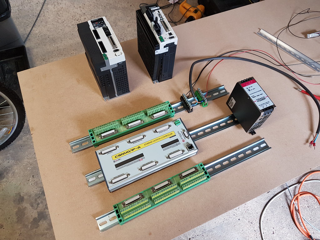
A quick video, nothing is really calibrated but the motor seems happy to spin to 4000 rpm. Its a Panasonic 1.5KW motor and A4 drive powering it.
https://www.youtube.com/watch?v=Az4RkyfsDTE
-
05-29-2016, 03:24 PM #3
Registered
- Join Date
- May 2013
- Posts
- 70
Re: Thor
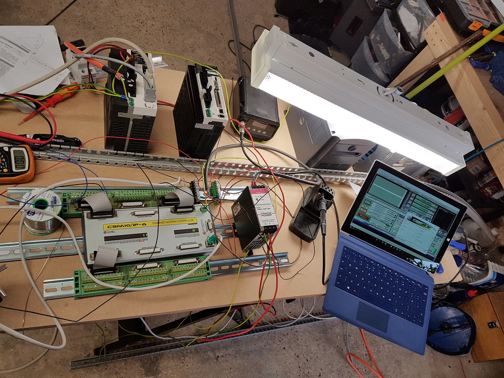
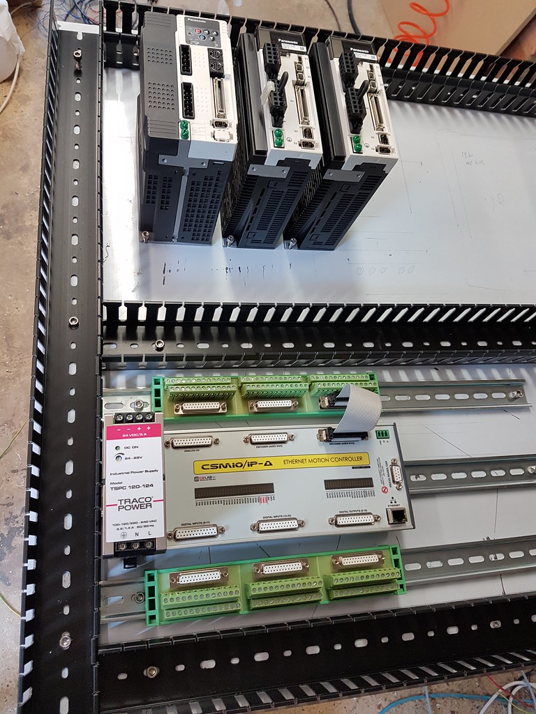
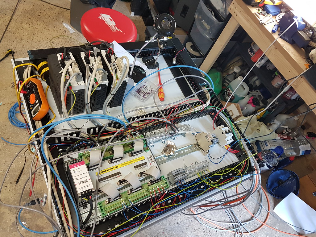
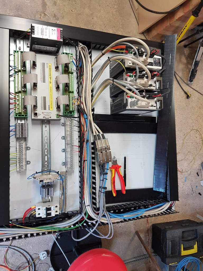
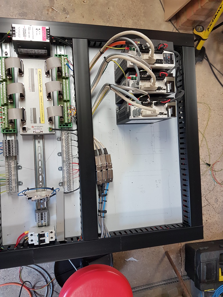
A number of hours later, some marking, measuring, drilling, fitting, wiring and we have the bulk of the electronics mounted.
-
06-05-2016, 07:08 PM #4
Registered
- Join Date
- May 2013
- Posts
- 70
Re: Thor
Electrics now mostly done. Running 2 of the 3 axis in the video below. I'm missing a plug needed for the 3rd drive but all tested and runs. I still need to wire up:-
Spindle (when I decide what Ill use)
Limits
E Stop etc
Some pics below showing the 'mass' of wiring and what it looks like near completed. Still need to remove the white protective cover from the plate.
https://www.youtube.com/watch?v=RLCvlyi4Z_E
-
06-12-2016, 09:02 PM #5
Registered
- Join Date
- May 2013
- Posts
- 70
Re: Thor
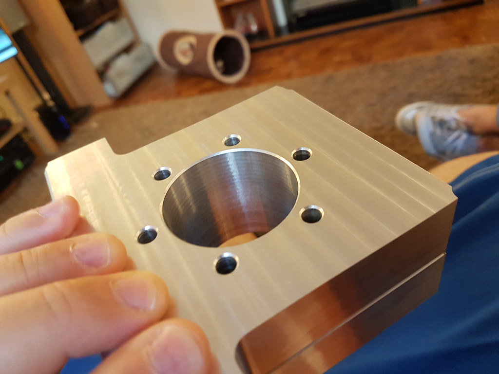
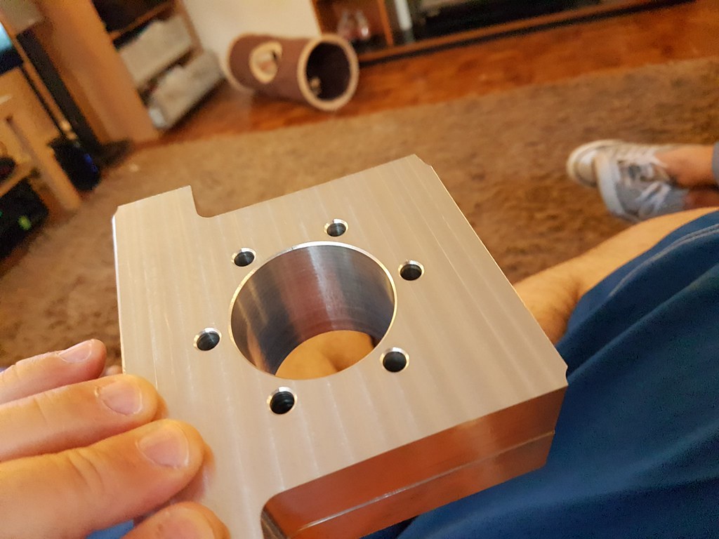
Starting to finish off the mold for the first casting as well as one of the bearing holders for my Y leadscrew.
The part was flipped over as its 50mm deep, my probe doesnt have the best accuracy so there is a 0.2mm or so step, doesnt affect the part however.
-
06-18-2016, 05:26 PM #6
Registered
- Join Date
- May 2013
- Posts
- 70
Re: Thor
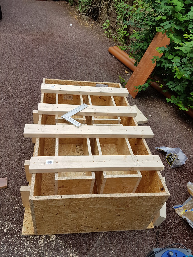
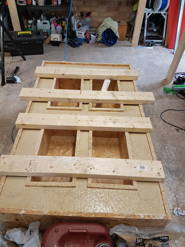
Managed to pour the mould today.
Some lessons learnt.
1. Make the mould stronger.
2. You use mix than you expect .... dont ask me where it all goes.
3. It's tedious .... just stick with it.
Here is the mix (0.2 water / cement) mix without superplastisizer.
https://www.youtube.com/watch?v=2IeEhFW44F8
Add some magic juice and it changes completely. Just to make it clear, the mix below has no more water, just 1.25l of plastisizer.
https://www.youtube.com/watch?v=4KfWcawy7b4
Just checked the pour now, still very liquid. One of the boxes moved but as it wasnt set yet I was able to fix it. Hoping that it will harden overnight.
-
07-01-2016, 11:28 PM #7
Gold Member
- Join Date
- Apr 2009
- Posts
- 5516
Re: Thor
The best stuff by far to use for forms is PSF (Phenolic Surface Film) plywood. Very smooth, hard, and stiff; and the glues used to bond the plies are water resistant. I would also treat the exposed edges with finish or wax or both.
-
06-18-2016, 06:35 PM #8
Gold Member
- Join Date
- Feb 2009
- Posts
- 2143
Re: Thor
So no wire, mesh, rebar, fiber at all in that pour? I think you are going to be disappointed... What is the solids recipe you used?
CAD, CAM, Scanning, Modelling, Machining and more. http://www.mcpii.com/3dservices.html
-
06-18-2016, 06:37 PM #9
Registered
- Join Date
- May 2013
- Posts
- 70
Re: Thor
Nope. I know its a bit contraversial. Suppose time will tell. Originally Posted by mcphill

1/3 Sharp Sand, 2-8mm Basalt Stone and 52.5R High Grade Cement with added super plastisizer.
-
06-22-2016, 12:53 AM #10
*Registered User*
- Join Date
- Jul 2014
- Posts
- 215
Re: Thor
You can always put in loose glass fibers instead of rebar. I think it would work very well for this application and is relatively inexpensive. They are often added to super plasticized concrete to improve the concrete's performance. Originally Posted by Chazaxl
You might consider doing that on the upper gantry since it will need to support more of it's own weight over a span than the base does. you could also lay the base on a 5-6mm high density rubber pad which would kind of help it self level as long as the bottom is pretty flat with no large distortions.
Paul
-
06-26-2016, 04:03 PM #11
Registered
- Join Date
- May 2013
- Posts
- 70
Re: Thor
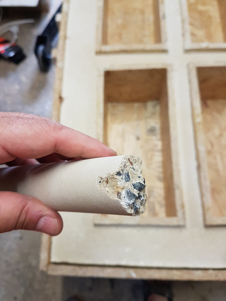
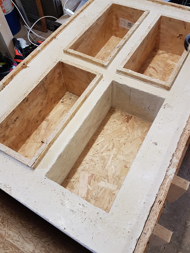
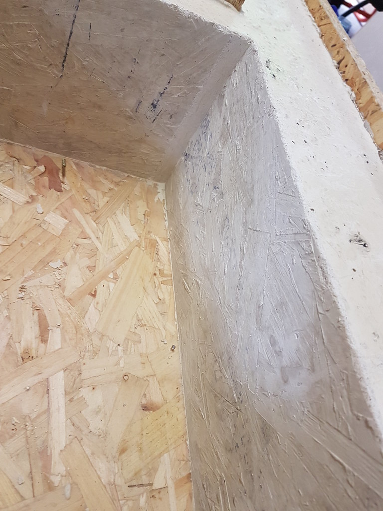
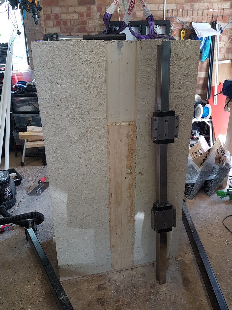
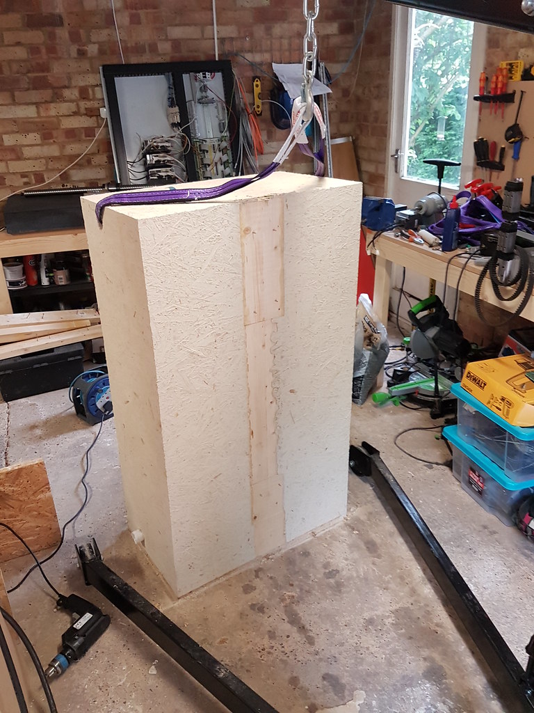
Some progress. Have removed some of the wood to see. Nice clean finish, no air bubbles (as expected with the plastisizer). Struggling to get the wood out, even with a mold release agent, its too tight to come out.
I need some advice on sizing some metal. I want to build a frame below the concrete to hold the mass and allow some castor wheels to be mounted. Estimated weight will be 2000kg when done. Can anyone suggest what size mild steel tube I can use?
Thanks
-
06-27-2016, 01:23 AM #12
*Registered User*
- Join Date
- Jul 2014
- Posts
- 215
Re: Thor
[QUOTE=Chazaxl;1903878]Some progress. Have removed some of the wood to see. Nice clean finish, no air bubbles (as expected with the plastisizer). Struggling to get the wood out, even with a mold release agent, its too tight to come out.
I need some advice on sizing some metal. I want to build a frame below the concrete to hold the mass and allow some castor wheels to be mounted. Estimated weight will be 2000kg when done. Can anyone suggest what size mild steel tube I can use?
Thanks
What's the largest size steel that you can work with? 50 x 50 mm square would be about the smallest I would use. 50 x 100 mm would be ideal with the long side oriented up and down. At least 3mm thick or more. Weld up a flat torsion box with mitered corners and several cross pieces that correspond to the walls of the base plus a couple of extra cross braces, and then weld a flat piece of steel at least 2-3mm thick on the bottom of the torsion box. It will be in tension if any part of the torsion box sags under the weight. Then fit your heavy castors in place at the corners. Make sure to grind and lap the top of the steel support structure flat so it doesn't introduce any stresses in the base.
You might also want to put some kind of thin resilient material of uniform thickness between the steel support and the cement base so that any imperfections in flatness of the base or structure can have less effect of throwing the base out of it's natural position.
You might also want to fill the open chambers in the base with a sticky expanding foam. It will strengthen the whole base and add more dampening without adding much weight.
-
06-27-2016, 07:46 AM #13
Registered
- Join Date
- May 2013
- Posts
- 70
Re: Thor
[QUOTE=Hezz;1904072]
Thanks. Appreciated. Originally Posted by Chazaxl
-
08-23-2016, 10:00 PM #14
*Registered User*
- Join Date
- Jul 2014
- Posts
- 215
Re: Thor
Looks good, how did you get the putty flat. Did you lap it with that surface plate?
It looks like you have a nice roll around steel stand for it. Maybe you should consider making the upper gantry and side beams out of steel and then fill them with cement. It will be much stiffer and very well damped.
Overall the project is looking good.
-
08-24-2016, 04:39 PM #15
Registered
- Join Date
- May 2013
- Posts
- 70
Re: Thor
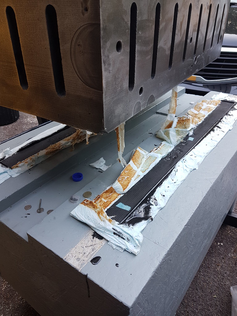
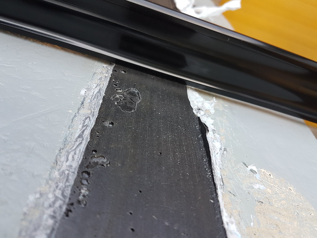
No, the flatness is created by pouring the DWH epoxy and then lowering a reference surface onto it like a mold. Once its lifted, it 'copies' the shape. So in my case I used a large 'block' of metal which is flat as my reference. Ill find more pics of this. Originally Posted by Hezz
Ye, the stand was a must, not only for levelling but the bottom structure is around 750kg, so not easy to handle.
I was thinking of that, easier than making another concrete structure but in the same breath, I dont want to cut corners on the design either.
Does anyone have a view on steel with concrete filled in versus a thick concrete structure?
Thanks for the comments.
-
08-25-2016, 01:14 AM #16
*Registered User*
- Join Date
- Jul 2014
- Posts
- 215
Re: Thor
I was thinking about heavy steel members filled with the high performance concrete. Not small tubes. 6-8mm sheet steel fabricated and internally braced to the shape that you had designed. Basically, my idea was to make the mold out of reinforced steel and It would out perform the concrete unless the concrete was made at least four times bigger or so. If it's steel reinforced in the center it's even better. It is so strong and stiff they use it for earthquake reinforcement on concrete bridges. Of course, this is your project and only you know what your budget and fabrication capabilities are. I don't mean to tell you what to do. The problem as I see it is that concrete does not flex very well without failure. And you will have to make your mold very precise to get the gantry just the right width to bolt it to the base. If there is a gap and you tighten it it may well crack and fail. There just isn't much room for manufacturing error in your design. But with a monolithic steel mold weldment you would have just a little flexibility and a good surface for lapping or grinding to get flat way mounts and Originally Posted by Chazaxl
Actually, I'm kind of the opinion that real heavy mass on the upper part of the gantry is not a good thing. For the base it's a good thing because it's a very rigid box type of structure, but the gantry is not and is prone to all kinds of vibration and resonance. And once this happens the mass is not in your favor. Once the gantry starts to vibrate the mass is a big problem. Stiffness and dampening and low to moderate mass I think are the most important features of a structure that is prone to vibration and resonance. The ideal gantry might be a structure that is steel skin on the outside and heavily braced with cement or EG fill near the bottom of the vertical uprights that attach to the base. But as you go up it might be better to have more bracing and a light weight sticky expanding foam or a EG constrained layer damped structure that limits the mass.
Just my two cents. I'm looking forward to what you are going to cook up for this project.
-
08-25-2016, 08:23 AM #17
Registered
- Join Date
- May 2013
- Posts
- 70
Re: Thor
Thanks. Appreciate the comments / input. Originally Posted by Hezz
I am a bit limited with respect to doing 'big' steel type of work. I dont have the ability to cut and move large plates easily. That said, food for thought. The concrete gantry would be placed in place and then 'bonded' with epoxy to make up the gap to ensure that I do not 'flex' anything when using rods / bolts. I have some 100 x 100 x 5 lengths left over from the build of the metal frame, not sure if there is any benefit in trying to create an 'A' Frame (side view) from it.
-
09-13-2016, 11:14 PM #18
Registered
- Join Date
- Apr 2012
- Posts
- 34
Re: Thor
What did you use? Originally Posted by Chazaxl
Show me
-
09-14-2016, 08:17 AM #19
Registered
- Join Date
- May 2013
- Posts
- 70
Re: Thor
Sorry, been busy. Originally Posted by danande
Place epoxy, (ignore the paper towel, the consistency was too liquid, but we created a dam for the epoxy). Then lower a reference surface (the 400 kg block used), let it dry, lift. The surface is not smooth (it copies the structure that leaves an imprint) but its flat.
-
06-26-2016, 04:18 PM #20
Gold Member
- Join Date
- Jun 2004
- Posts
- 6618
Re: Thor
I think the toughest part of the releasing is caused by your mold material choice. OSB would not release well even if you had steep draft angle built in.
A better choice would be melamine. Almost as cheap and would release cleanly with little effort and leave a smooth surface.
As for the base, if you have Fusion 360, it can help with the base design. This is one area where it really does not hurt to over build. You don't really want something that will do the job, but with borderline specs.
Consider longevity of the base too. It will spend it's life supporting that weight. Not just when the lights are on.
Lee

 Reply With Quote
Similar Threads
-
Free MJOLNIR THOR HAMMER GIVEAWAY
By silverfoxx03 in forum Machine Created ArtReplies: 0Last Post: 03-27-2012, 01:44 PM -
MAJOR PROBLEMS with Thor 45cc 2 Stk Petrol engine....PLEASE HELP!!!
By thkoutsidthebox in forum Hobby DiscussionReplies: 6Last Post: 10-18-2011, 11:12 PM
