


And the hits just keep on coming! Amazing how many stupid decisions/actions were taken in building these machines. Most/all of the ones I am aware could have been done MUCH better for no more money! I just don't get it...
Thread: More Mikini Modifications
Results 21 to 40 of 50
-
06-02-2013, 12:43 AM #21
 Gold Member
- Join Date
- Feb 2009
- Posts
- 2143
CAD, CAM, Scanning, Modelling, Machining and more. http://www.mcpii.com/3dservices.html
-
06-02-2013, 03:59 PM #22
Registered
- Join Date
- Mar 2009
- Posts
- 199
I am pocketing it out so I can remove the Z axis stepper without having to remove the column.
-
06-02-2013, 07:24 PM #23
Registered
- Join Date
- Jul 2006
- Posts
- 367
That would sure make things easier Originally Posted by howecnc

 I also looked at what would be involved in moving the Z stepper to the top of the mill. I think it's doable and I thought about doing it, but, I need to get the machine up and running....maybe in the future....
pete
I also looked at what would be involved in moving the Z stepper to the top of the mill. I think it's doable and I thought about doing it, but, I need to get the machine up and running....maybe in the future....
pete
-
06-02-2013, 09:42 PM #24
Registered
- Join Date
- Aug 2010
- Posts
- 599
Interesting find! They must of fixed that issue at some point because that area on my mill is open. I could take off the stepper from the underside if I wanted. I also notice the Z column flex with a dial indicator when I pull down or push up on it. I though that was normal but maybe not. I seem to be avoiding the Z stalling when I eliminate vertical rapids and keep the Z motion nice and slow, so I wonder if it is just too much weight for the stepper motor to handle and that speed (100IPM and slow acceleration). Fortunately I think it would be easy for me to replace the Z since I don't have to take off the column. I still wonder though how they tram it from the "factory" with no way to adjust it.
What is the main argument against using servos? Cost? It seems a much better way to go after having busted so many tools and parts from loosing steps with no positional feedback. I become paranoid about taking my eyes off of it for 5 sec. In fact I basically just stand there with my hand over the E-stop. That sucks for an hour long program.
-
06-02-2013, 11:58 PM #25
Registered
- Join Date
- Jul 2006
- Posts
- 367
Swath, I don't think they really tram these things. The just rely on what ever their machining process gives them. I never saw any kind of inspection sheet stating its accuracy, or that its was even done. On my mill I can see where they actually took a disc grinding wheel on a portion of the base where the column sits on. Fortunately, my spacers are sitting on a machined section.
I also checked my Z settings in Mach. The velocity is 75 and acceleration is 50. With the old stepper it handled the new AC motor with no issues. When was the last time you checked how accurately your XYZ are over a known distance??? I do this every time I change something....a setting, a new drive, stepper, etc.
As for servos, that would be an entertaining venture. The cost as well as the learning curve can be an issue. I think if I wanted to go with servos, it would be time for a new machine...something like the new Novakon Torus Pro with servos.
Today, the wife and I went out to see some friends (Day labor blues band) play at a benefit concert. Had some great food, sweated a ton..thanks to the heat.
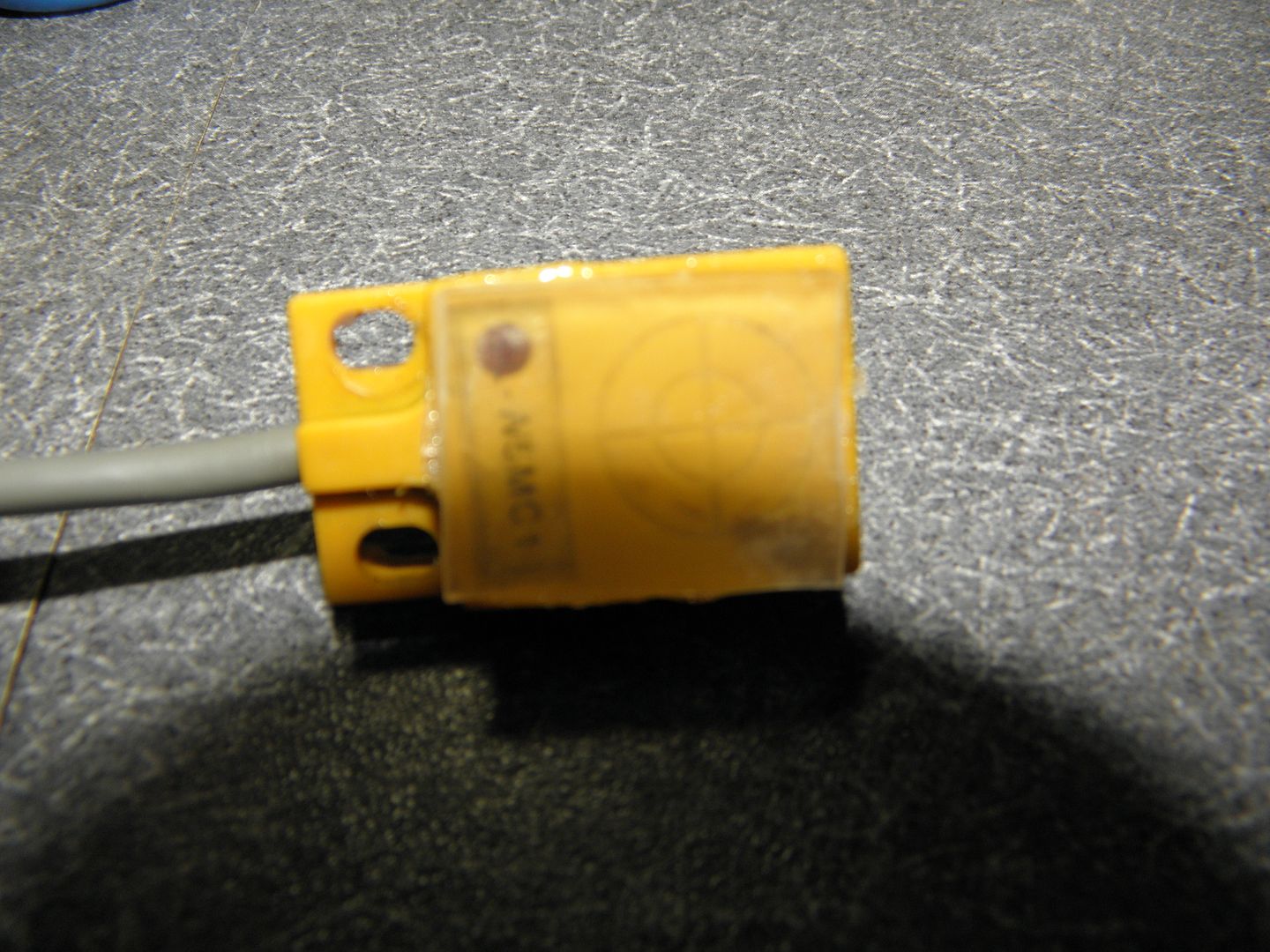
When we got home, I changed into my work clothes, went into the shop and played with the mill. I did some experimenting with my proximity switches. As many of you know, these switches are really accurate and work well. But, you will get that occasional tripping and then you will have to reset. All my machining is with aluminum and I don't know how many times a piece of aluminum will find its way and attach itself to the contact area of the switch and set off an e-stop.
On another forum, someone (I believe it was Ray L.) mentioned encasing the switches in some type of non conducting medium..plastic, HDPE, etc. Where the thickness of the plastic in the sensing area was just enough that aluminum would not set it off, but, steel would. Hmmmmmm.
I kept thinking these things are sealed pretty good and decided to go a different route. I found a plastic box and measured the thickness of the lid... it was .060". I hooked up the sensor to a 12 volt supply (Brown lead positive, Blue lead negative) and passed a steel bracket over it and the led on the sensor came on. I then put a piece of the plastic on top of the sensor and passed the steel bracket over it, again the led came on again.
With the plastic piece still in place, I passed over a piece of aluminum over the sensor and the led did not come on..even pressing against it, the sensor led would not come on....
Here's my ghetto solution....I simply super glued a piece of plastic to the switch.
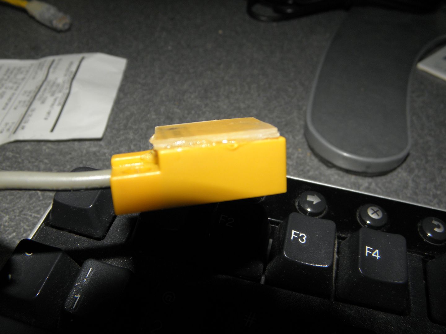
Ok, maybe a bit to much super glue. I'll be neater with the ones going into the mill
Hopefully this will cut down on the nuisance re-set situations.pete
-
06-03-2013, 07:01 PM #26
Registered
- Join Date
- Mar 2009
- Posts
- 199
I think I am going to replace mine with a mechanical switch.
-
06-03-2013, 07:11 PM #27
Registered
- Join Date
- Aug 2010
- Posts
- 599
Hmmm, that must be another fix. My stepper power supply is 72v so I guess conceivably I could just add a bigger NEMA 34 stepper to the Z. I guess maybe another driver too. 99% of the time all my axes jog fine at 100IPM, but it's that 1% where a stall becomes a calamity. Reducing all my Z rapids to 20 IPM seems to have reduced the mean time to failure to about 0.5% or half of what it was. Still sucks, ruined some more plaques and broke an engraver yesterday thanks to the mysterious stall. This morning everything went fine on a 1.5 hour program then literally in the last 30 sec. Z stall on a retract (20IPM) then plunge right into the work. Sometimes I wonder if this machine is cursed. Anyone think a smooth stepper might help?
-
06-03-2013, 07:35 PM #28
Registered
- Join Date
- Jul 2006
- Posts
- 367
Swath, have you tried just switching the drivers...x with z or y with z ?????
pete
-
06-03-2013, 07:47 PM #29
Registered
- Join Date
- Aug 2010
- Posts
- 599
No I haven't, the stall happens so randomly and infrequently it's hard to trouble shoot. I can try doing that and just cut air for a long time, then come back to see if it's still on position, and if not then on what axis the stall occurred. Is that what you are thinking?
-
06-03-2013, 08:22 PM #30
Registered
- Join Date
- Jul 2006
- Posts
- 367
Yep, see if the stall happens to x, if that is the one you switched. Originally Posted by SWATH
pete
-
06-04-2013, 12:00 AM #31
Gold Member
- Join Date
- Feb 2009
- Posts
- 2143
When I put my USB SmoothStepper on ALL the motions seemed SO much better. I think it is certainly worth a shot before doing to many other investments. If you don't like the SS, there should be a reasonable aftermarket to sell it back in to...
CAD, CAM, Scanning, Modelling, Machining and more. http://www.mcpii.com/3dservices.html
-
06-04-2013, 01:08 AM #32
Registered
- Join Date
- Jul 2006
- Posts
- 367
mcphill, you really have a good point there. I don't think I would run any Mach based machine without one Originally Posted by mcphill
pete
-
06-04-2013, 04:10 AM #33
Registered
- Join Date
- Aug 2010
- Posts
- 599
I'm thinking about doing that. Do you guys know if the ethernet jack on the Mikini integrated computer works? Mine is full of black silicone but I wonder if I pick it out if I can use an ethernet smooth stepper.
-
06-04-2013, 09:37 AM #34
Registered
- Join Date
- Jul 2006
- Posts
- 367
The jack does work, but it's a pain to clean out ... Actually , my son uses the Mikini computer now in the basement to surf the Web Originally Posted by SWATH
pete
-
06-08-2013, 02:05 AM #35
Registered
- Join Date
- Sep 2009
- Posts
- 45
I would love to see the honker on there. Since it is 3KW would you have to upgrade the amp rating of anything to handle it? Wouldn't that be jumping from ~10A to ~13A? I don't know what the Mikini electronics are rated for in reality but Phil told me something like the 20A circuitry is actually rated for up to 30A.
I would just love to see some kind of motor work correctly without too much hassle especially an AC servo.
Wow Pete, those are huge motors. One reason the spindle sounds so solid with the large motors is you now have a giant giroscope mounted to them. Every time a cutter takes a bite, it twist the spindle ever so slightly, but now the spindle has a massive giroscope on it that is being rocked back and forth with each cutter bite---and big giros resist rocking.You could get the same effect using the original spindle if you mounted it on a stiff three-foot-long pole (not exactly practical, but do-able). Another reason the cutter cuts smoother is probably that it has all the inertia of the big motor's armature. This leads to smoother cuts, but it also leads to bigger shocks on the spindle bearings (I think Phil from Mikini alluded to this in his conversation with Allen). This may shorten the life of the bearings, but it doesn't sound too hard to replace them from Allen's post.
-
06-14-2013, 04:49 PM #36
Registered
- Join Date
- Dec 2008
- Posts
- 263
I just stumbled accross this thread having been busy with my G0602 lathe cnc conversion. Wow Pete you have been busy, nice work on all the mods man.
SWATH sorry to hear about your kid, and glad to hear he is doing better.
-
06-14-2013, 05:18 PM #37
Registered
- Join Date
- Aug 2010
- Posts
- 599
Thanks Allen, we're just trying to put it behind us as best as we can and move on although being at the hospital is becoming our new way of life it seems. Maybe I'll trick this machine out well enough to keep it and pass it down to him as a relic of being dealt a crappy hand and overcoming it through perseverance and ingenuity.
-
06-15-2013, 02:43 AM #38
Registered
- Join Date
- Jul 2006
- Posts
- 367
Allen, good to hear from you Originally Posted by allenj20
It's been a busy, kinda of nerve racking week. I took a "Honey Do" vacation this past week, mostly to finish our front porch (which has only been in the unfinished state for 4 years...ouch!!! and believe me the wife let me know it...lol).
Anyway, I did have a chance to work on the mill...thanks to a bunch of rainy days and waiting for joint compound to dry. I installed all the limit and home switches. This was kinda of time consuming, as I had to make all new brackets and drill new mounting holes on the mill.
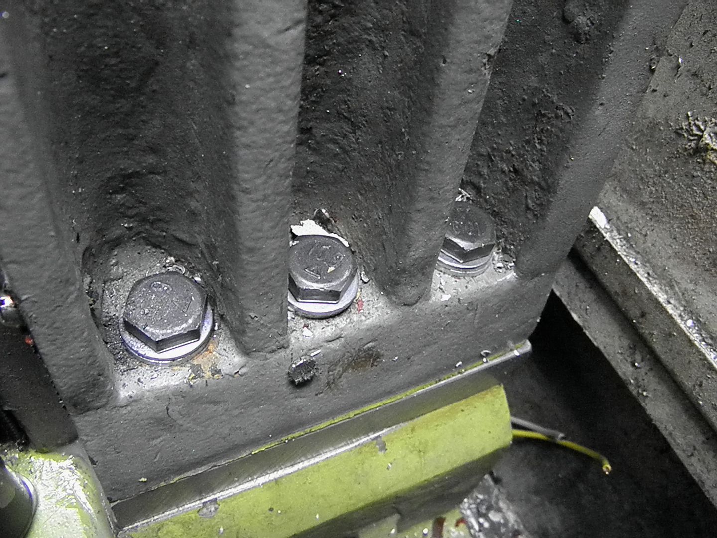
Next I made up my 1" spacer blocks for the column (thanks to Mikini engineering), so that I could use my new Z motor. You can see it here, as well as the new bolts and washers.
Since I was installing new steppers, I thought of replacing the stepper to ball-screw couplings...maybe stainless steel units. But, there is a problem...I could not find couplings that would fit. The Mikini..at least on mine are 50mm long by 34mm in dia. The longest one I could find was 45mm. I was a little concerned with the amount of bite the smaller coupling would have and nixed the idea and used the old ones.
One thing that bothered me about the mill for some time was the number of conduits inside the milling area. I reduced it to one......The X axis motor and switch lines.
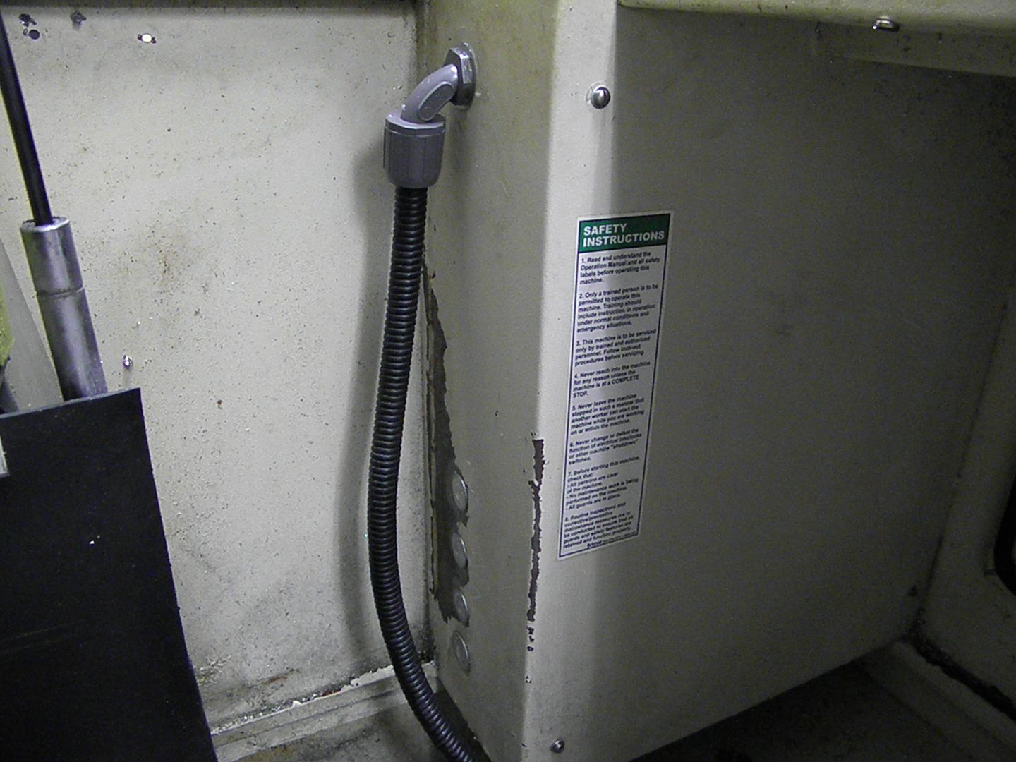
I used electrical knockout covers to cover the old holes and silicone them in.
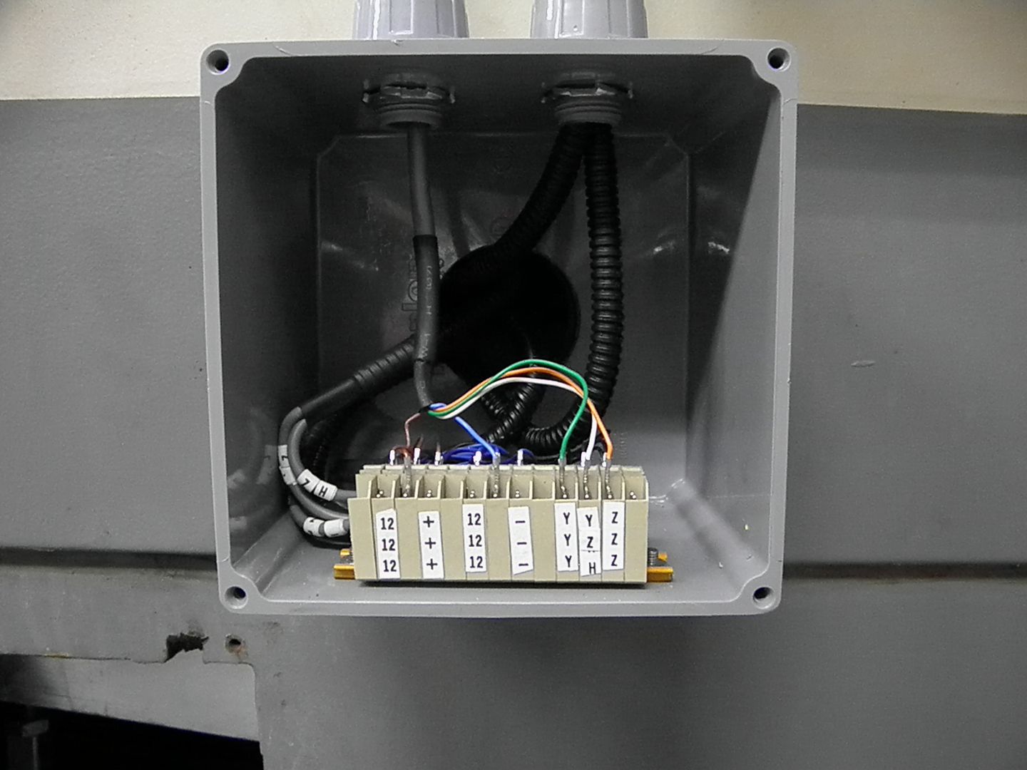
All the wiring has been re-routed to the back of the machine...Here are the Y and Z limits and homing lines...
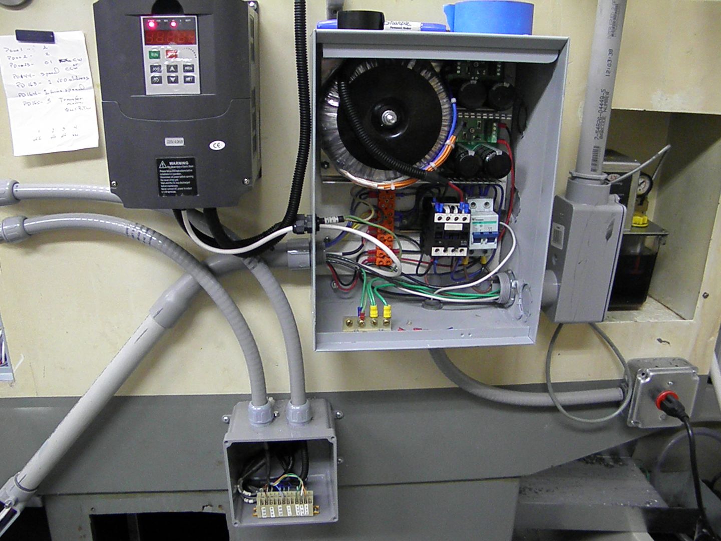
and the VFD, power supply...
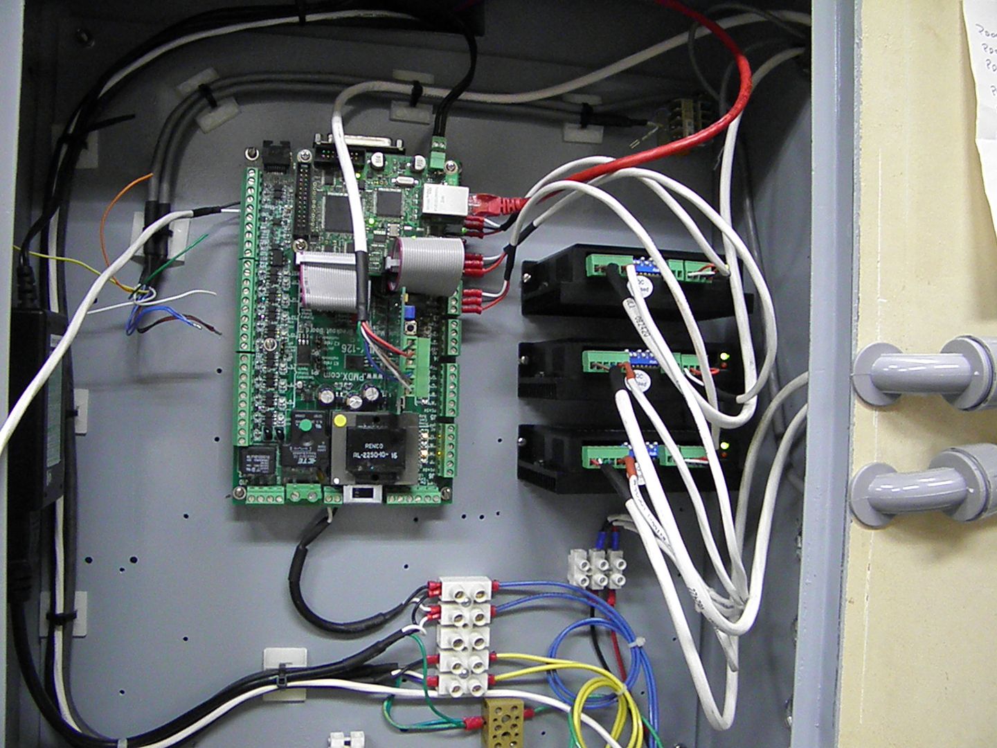
Here is the PMDX 126, Ethernet Smoothstepper nestled into their new home...
Now for the Murphy's law stuff...first I had a problem with the PMDX board and the VFD playing nicely together. The main issue was that I didn't have any torque at 3600 rpm..which is the rated speed of the motor. The motor ran great with the panel mounted potentiometer, but, for some reason under Mach3 PWM spell...no luck. The VFD is rated at 3kw and the rated amperage is 11 amps..the same as the motor.
Naturally, this took up a bunch of time, trying this and that. That's when I went over to my lathe (which I also converted).... it had a 4kw VFD, rated at 17 amps... What the heck, I thought. I moved the 4kw VFD to the mill and it worked. I took it down to 1000 rpm and could not stall it
But, now my lathe is in need of a VFD... fortunately, the lathe is over powered with the 4hp motor and I was able to get a new motor today. A brand new Baldor inverter duty 2hp, 4 pole motor...the best part, only $130.00 on ebay and it's a local pickup. It even has an encoder. Should work well with the Hitachi vector drive that I originally bought for the mill.
Another issue I had were my connections. I thought I would solder the ends of all the signal wires and the motor leads and eliminate frayed ends, when inserting them into the connectors. What I didn't know was that as i would tighten down on the screws, the wire kinda squirted out just enough to make a poor contact...thus causing me to chase my tail for a couple of days.
Problems like no movement of the axis's, The Z axis sounded like it was jammed tight...I could go on, but, I want to move forward....Anyway, I redid all the connections and re-inserted them naked I turned everything back on...went over to the keyboard and pressed some buttons and I had movement on all the axis's !!!
I messed around with some motor tuning's and everything sounds so smooth.
Lastly, I did a quick check on my tram and found that I'm leaning forward by .002". and leaning to the right .0015". When I trammed the mill sometime ago, it was out by .004" on both readings. I'll do some shimming tomorrow
All that's left is to hook up the coolant pump to a relay, connect the limits and homing switches and get the probe in place. One last thing, I may have an opportunity to get the rotor in the mill motor precision balanced...some friends from my electric motor winding days offered Some Kluber grease in the bearings... Mmmmm, 12,000 rpm could be a possibility .....
more to come....pete
-
06-15-2013, 02:02 PM #39
Gold Member
- Join Date
- Feb 2009
- Posts
- 2143
Do you have any details on what you did with the limit and home switches?
CAD, CAM, Scanning, Modelling, Machining and more. http://www.mcpii.com/3dservices.html
-
06-16-2013, 12:44 AM #40
Registered
- Join Date
- Jul 2006
- Posts
- 367
Nothing really special. I just used some aluminum angle and flat bar to make the new switches work. I left myself about .500" play to the end of the screws, just in case I over shoot the limits. I used a .010" feeler gauge to set the distance from the switch to the parts that will set them off... Originally Posted by mcphill
Here are the "Y" limit and home switches, they needed a .375 block to get them to where I needed them.....
The switch on the other end is basically the same
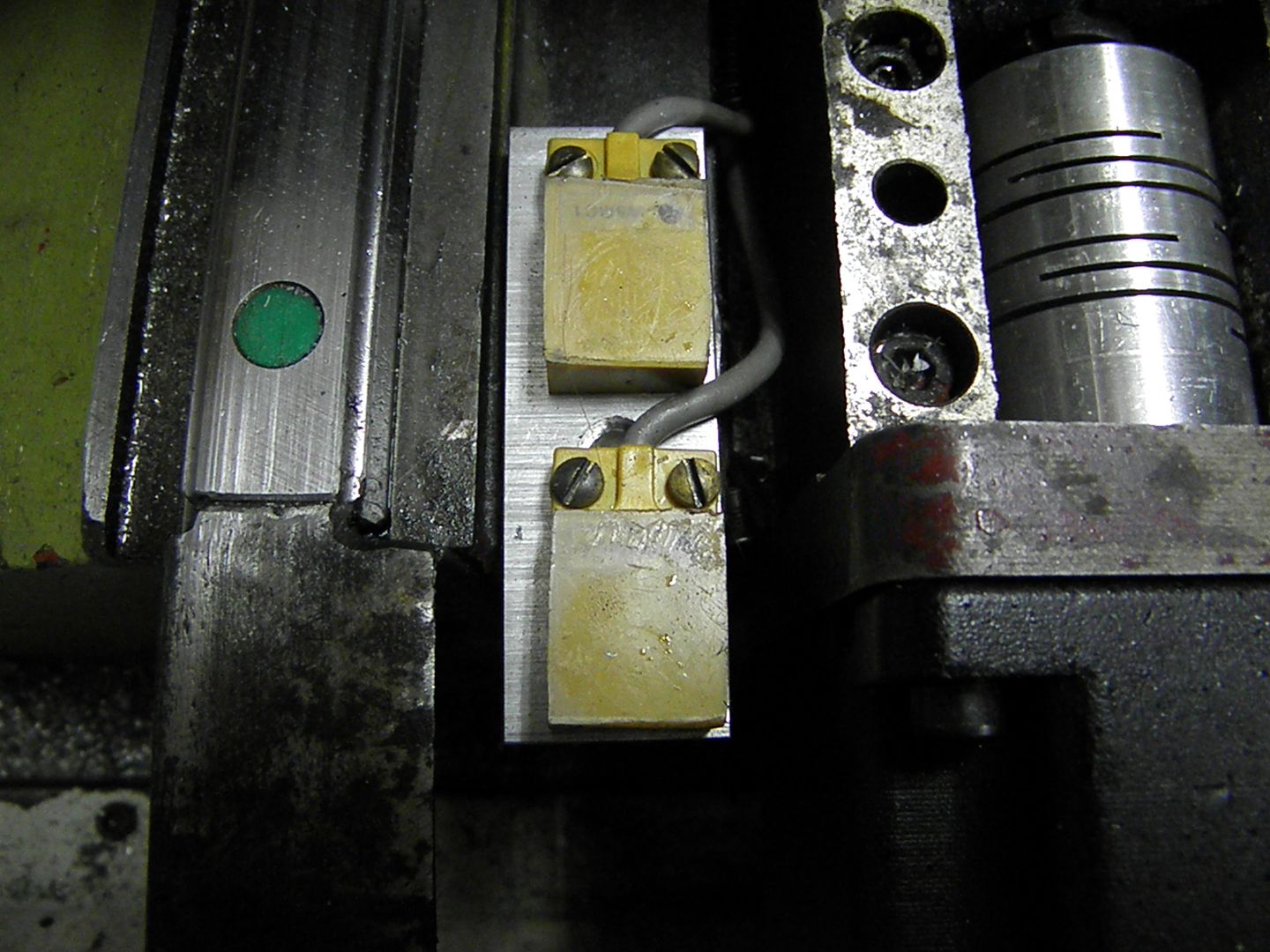
Here are the "Z" switches.....
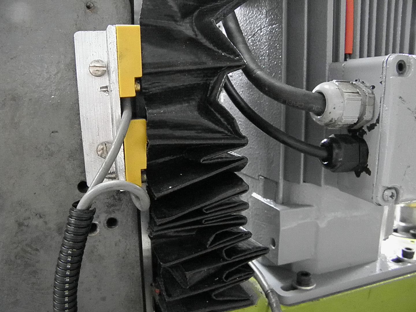
and the bottom one (a little fuzzy)....
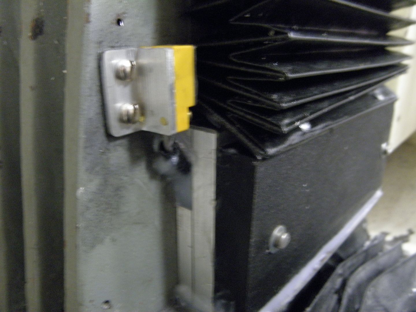
In the above picture, you can see where I filled in the space behind the black cover. This was an open area about .750" . I figured I block it up to stop some of the swarf and coolant that was getting into this area and down into the Z stepper pit.
I also picked up the motor that I bid on Ebay for $130.00......
C-face
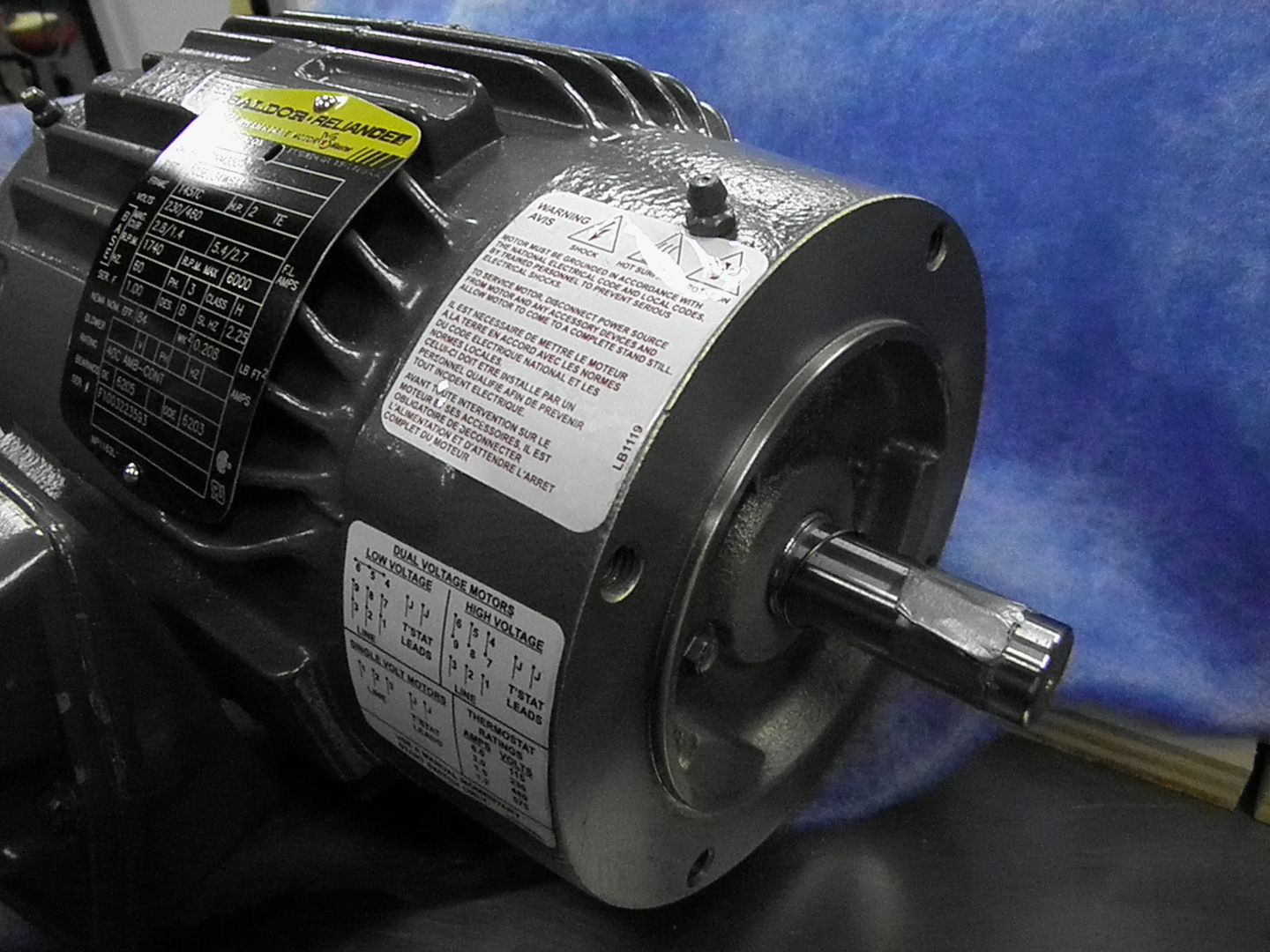
and it has feet
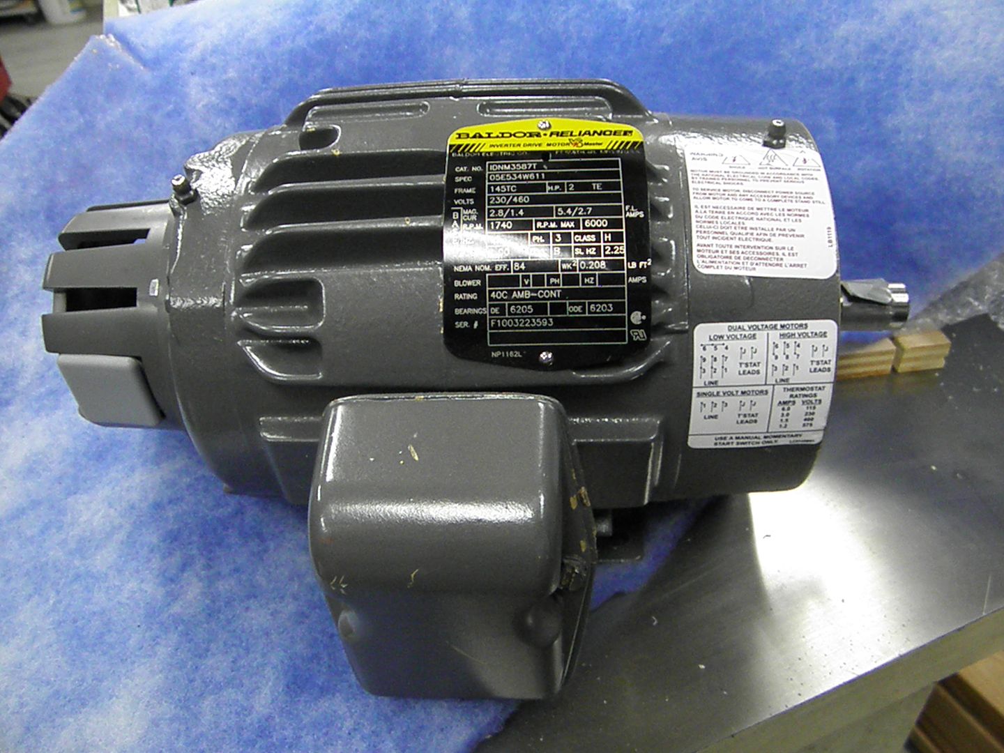
It's all cast iron and weighs about 62 lbs. I also liked the name plate's max rpm I thought it had the encoder installed, but, no such thing. I have a couple encoders laying around. Maybe I'll play around with them when I get some free time.
Lastly, I trammed the mill today. It took some time, but, I think I nailed it. -X and +X are dead on, as are the Y's. I used a .0005 dial test indicator to get the results.
Tomorrow, I'll try to finish the wiring and do some motor tuning. I did have a chance at running the motors at 250 ipm. But, i think I'll settle out at about 120 ipm.
I'll try to get a video of the motors in action...
more to come....pete

 Reply With Quote


Similar Threads
-
SYIL X4 - Modifications
By mikie in forum Syil ProductsReplies: 23Last Post: 08-16-2011, 04:41 PM -
Modifications to my CNC Machine
By patchwork in forum Shopmaster/ShoptaskReplies: 3Last Post: 03-29-2011, 12:51 AM -
Cnc Modifications Links
By plasidboyy in forum DIY CNC Router Table MachinesReplies: 1Last Post: 01-08-2010, 06:29 AM -
Rockcliff Modifications
By alien_X in forum Uncategorised WoodWorking MachinesReplies: 5Last Post: 01-11-2009, 01:09 AM -
BOSS 8 modifications
By jonny in forum Bridgeport / Hardinge MillsReplies: 10Last Post: 02-17-2006, 06:13 PM
