


Confirming the capabilities I milled a real part from a steel blank today. Well, it is a fantasy part without any particular use except to practice. It ended up quite nice. Accuracy in y-direction is about 1/1000" oversize and in x-direction about 3/1000 inch undersize. The 10 and 15mm holes are milled as pockets with the 1/4" bit and look good as far as i can see with the caliper but I need to take it to work and measure with pin gages to get a better result.
So far so good and I will use it when needed but machining steel is a bloody mess with the sharp and magnetic chips flying everywhere. I will avoid it if I can and stick with the real stuff, that is wood
Machine setup:
Finished part, top:
Finished part, bottom, almost looks like a Geneva Stripe pattern
[ame=http://www.youtube.com/watch?v=WuSygxzvCKM]MachiningSteelPart.avi - YouTube[/ame]
Results 381 to 400 of 645
-
02-17-2013, 01:47 AM #381
 Registered
- Join Date
- Aug 2011
- Posts
- 999
-
02-17-2013, 02:07 AM #382
Registered
- Join Date
- Mar 2011
- Posts
- 584
Nice work what were ur feeds n speeds?
My CRP 48 x 48 build http://www.cnczone.com/forums/open_s...3-crp_4x4.html
-
02-17-2013, 02:51 AM #383
Registered
- Join Date
- Jun 2012
- Posts
- 817
That turned out pretty nice. I've been thinking about trying the same thing one of these days just to test my machine. It proves that bamboo is pretty rigid stuff!
-
02-17-2013, 04:00 AM #384
Registered
- Join Date
- Aug 2011
- Posts
- 999
9000 rpm, 20 ipm, 0.02"pass depth, 0.25" 2-flute carbide cutter, roughing in climb mode and a conventional direction finish cut. Originally Posted by vtx1029

The surface speed was rather high about 600 sfm but good coated endmills should handle that for light cuts. Since I did not use real coolant the cutter may not live that long but I started spraying WD40 when I saw some chips coming out blue.
-
02-17-2013, 04:19 PM #385
Member
- Join Date
- May 2012
- Posts
- 231
Blue chips are good on a milling machine doing steel.That means that the chips are removing most of the heat from the work piece. Instead of the bit building up heat in it. You used your head on doing the depth of the cut too. The only thing I would suggest is using a 4 flute bit instead of the 2 flute bit I think your cutting would be a nicer. Or at least nicer looking. But then again you did do this with a wood based gantry. Good job nothing like pushing to the limits.
-
02-18-2013, 09:11 PM #386
Registered
- Join Date
- Aug 2011
- Posts
- 999
Ah thanks, I did not know that. Actually I have never used a metal mill in my life and thought it was overheating. If I do another experiment I will order a 4-flute bit. But as mentioned earlier I find machining steel kind of unpleasant. While my CNC machine's moving parts are well protected, the barbed chips get stuck under the shoes and in clothes and my wife already complained that I am leaving a crunchy chip trail all over the deck and den. Originally Posted by dodger889
-
03-06-2013, 06:37 AM #387JerryBurks Guest
For now I dropped all that metal milling foolishness and will pick it up only when I really need to. At least I know I can do it

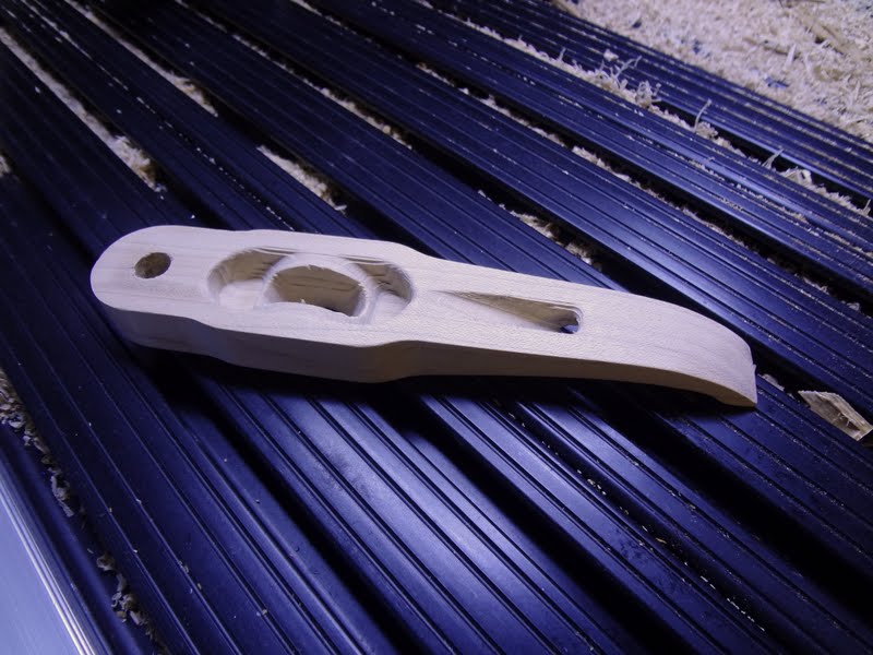
Instead I dusted off the rotary axis and made an experiment in 4-sided indexed machining for some homemade low-profile clamps. So far I have been using mostly the blue aluminum Rockler hold-down clamps but with the knurled knobs sticking out high I broke already a few bits and milled anyway into the clamps a few times. My new experimental clamps are quite shallow and can be used on top of the blanks like usual or with a screw or dowel into the side of the blank. I am using bronze carriage bolts (expensive, but nice to my aluminum t-slots) and so-called weld-nuts with a flange (cheap). Let's see how that works.
4-sided machining of a 3/4" x 1.5" Maple rod
Came out quite nice:


-
03-06-2013, 07:45 AM #388Trotline Guest
Very nifty clamps there! I confess, I use a junkyard dog clamping system. Just disposable slats with holes for the hold-down bolts. Oddly enough, I've yet to crash an endmill into them..
Luke
-
03-06-2013, 02:01 PM #389BanduraMaker Guest
Looks really good Jerry!
How did you go about aligning your 4th and tailstock? I've got mine wired in but other projects have kept me from getting it up and running. I'm still struggling in my head with how to align the darn thing too.
-
03-06-2013, 05:12 PM #390JerryBurks GuestI know, I tend to over-design things. The real reason for me milling into clamps is probably because I am a penny pincher when it comes to lumber and do not allow sufficient clamping margin. Originally Posted by Trotline
-
03-06-2013, 05:25 PM #391JerryBurks GuestWell, that is a real good question and I have not fully solved it yet. The rotary axis and tailstock are both mounted on precisely square cut plywood plates with attached 5/16" aluminum bars that slide in the table t-slots. That gets me quite close, maybe 10-20/1000" off. Originally Posted by BanduraMaker
It is actually a smaller problem for continuous rotary machining. If you are off a few 1/1000" the part may come out a bit thinner or thicker or conical but in that order of magnitude it is not noticeable for most parts. For my precision ballscrews that I did last year that was however not acceptable and I had to machine 2 annular grooves at each end of the stock first, measure with a caliper and recalculate the G-code to correct for the difference between nominal and actual groove diameter. But I could do that because I generated the G-code anyway with a separate program and not CAM software.
For the multi-sided indexed machining this is a different story. If Z and Y are not perfectly zero'd on the rotation axis and the tailstock/chuck center perfectly parallel to X you will get visible steps. A few 1/1000 is already too much. For the clamps I got it close enough so that I could sand the steps off but I am also still looking for a better way of doing that. Since I don't think I can set the axis and tailstock up with better than 10 or 20/1000" accuracy as mentioned above I may employ a similar method as for the ballscrew. That means to machine some kind of part from a scrap lumber first, measure the errors and feed the g-code through a custom postprocessor to correct. The one positive thing about the rotary machining is that it does not matter much how you clamp the material in the chuck or tailstock as long as the machining takes place within the material envelope. The only reference that counts is the rotation axis.
The other issue is just the learning curve of using the rotary axis CAM (I use DeskProto). Before I got this clamp right I probably screwed up 5 other pieces because of programming errors. No problem here and only time wasted but for a larger part from exotic lumber that can be painful. It is almost mandatory to test the code on a cheap piece of wood first.
Maybe I just make such parts the old fashioned way with manual flip and dowel alignment
-
03-06-2013, 06:52 PM #392BanduraMaker Guest
So here was my thoughts on what I'm going to try. Keep in mind that I have a 4 jaw independent chuck. I picked up a length of .75" drill rod which should be pretty uniform in straightness and diameter, If I recall, it should be better than .001.
Step one would be to use a test indicator to get the drill rod aligned in the center of the rotational axis in the 4-jaw chuck
2) touch off to the top of the bar using a square edged tool (i.e. a dowl pin or something like that). Using this info, you should be able to accurately figure out the Z-height of the center of rotation.
3) move along X and do the same thing to make sure that the axis is parallel to the table. Shim as necessary
3) with the test indicator mounted to/in the spindle, set it so that the point is at the Z-height of the axis of rotation.
4) jog along X and check at multiple locations. "rotate" the 4th axis as necessary to get it aligned.
To align the tail stock is more difficult. My thought was that for now, I'd use my lathe to center drill the drill rod and simply eyeball it into the center hole. The big issue is that this would take a new length of drill rod for every stock length.
For the most part, I should be able to keep my 4th axis mounted to my table and it won't interfere with any standard 3 axis jobs I'm doing. The only problem would be with sheet goods longer than my table and for low Z- height, my dust shoe can hit the chuck. Leaving the tailstock mounted would be a problem.
I've had the thought of making a fixture that mounts the rotary axis and tailstock in perfect alignment with some sort of gib or something like that for the tailstock to slide along. The only issue with that is that with my rotary axis 1/2" off the table, it's pretty much centered in my gantry clearance so whatever I come up with would have to be 1/2" tall at the mounting points for the axis and tailstock to not eat into my maximum stock dimensions.
-
03-08-2013, 03:02 AM #393
Registered
- Join Date
- Aug 2011
- Posts
- 999
I found aligning the chuck itself allows for some (minor) error. If the direction of the rotation axis out of the gearbox is off only a little, the live center of the tailstock (if used) will just force it. For my gearbox mount, clamping it flat to the table and guiding the direction with a tight fitting bar in the t-slot is pretty accurate (better than 0.1 degree). Therefore I am not so worried about that part. Originally Posted by BanduraMaker
That is also currently my main problem. But thinking about it, I decided today to rebuild the tailstock with a mechanism to make the live center tip adjustable a few millimeter in Y and Z direction. You don't really need a continuous rod from the chuck to the tailstock. I am planning to turn a short cylinder with the exact diameter of the rotating live center tip and clamp that into the chuck. With 2 dial indicators at 90 degrees on a bracket dangling from the spindle I can then find a reference for Z and Y at the chuck end, move over to the tailstock and adjust the live center tip to match the reference values from the chuck side. Sounds simple enough in my mind.... Originally Posted by BanduraMaker

For the precise tool zero setting I will probably fabricate an electrically isolated metal cylinder that can be used as touch "plate" for Z and Y . Interesting challenge.
-
03-08-2013, 05:44 AM #394
Member
- Join Date
- Apr 2007
- Posts
- 1955
If you use the head stock of a metal lathe + chuck rather than a wood lathe chuck in the 4th axis, it might make your life easier. A metal lathe chuck has a hole through it to allow rods and tubes to pass completely through it, so you don't need a dedicated rod length for each project.
It might not matter, but I think that the hardened thompson rods are spec'd even tighter than drill rod.
-
03-08-2013, 05:13 PM #395
Registered
- Join Date
- Dec 2010
- Posts
- 634
Jerry and I both have the same 4th axis which uses a harmonic drive which doesn't have a through hole. I actually do have a metal lathe chuck mounted on mine but you can only slide the drill rod back until it hits the face plate. Originally Posted by harryn
-Andy B.
http://www.birkonium.com CNC for Luthiers and Industry http://banduramaker.blogspot.com
-
03-10-2013, 05:56 AM #396
Registered
- Join Date
- Aug 2011
- Posts
- 999
Quite a productive day. I cut the parts for the new adjustable tailstock and assembled everything. I still need to get 2 cheap dial indicators and fabricate a bracket for them and a 42mm diameter cylinder to match the live center tip diameter.

-
03-20-2013, 04:31 AM #397
Registered
- Join Date
- Mar 2012
- Posts
- 68
I am about to order one, but I have a couple questions about the 4th axis you are using from ebay.
I assume you are using the stepper that came with it, if so what is the speed, acceleration, and steps/in (or is it called steps/degree) in mach 3 set to? Is this a good stepper, or should I order it without it and find another. I think I missed it but what kind of driver and power supply are you using for the axis. Right now I have a 878oz kit from longs motor on my machine.
How hard is was it to mount another chuck, like a nova chuck.
I understand that the z and y need to be zeroed to the center of the 4th axis, but how do you zero out the rotational axis for 4 sided machining, like if you put a 2x4 in blank in it and wanted to start on a 4in face?
Wondering if you have thought of probing the harmonic drive casing (each side and top) to set the y and z zero? Using a grounded bit and 5v in the casing, like the 2010 screenset does. Probe -y side, probe +y side, get y 0 from the center of those two, probe top, get z 0 from know distance down to center of the axis. This could also be used to calculate the squareness of mounting in the 4th axis
-
03-20-2013, 07:59 PM #398
Registered
- Join Date
- Aug 2011
- Posts
- 999
I think this little stepper is appropriate for what I need. I can get it to spin about 20 rpm reliably and the output torque is more than the harmonic drive can handle anyway. I use it with Gecko203V drive and a 72V linear power supply. With a 48V supply the max speed is probably somewhat lower. The rotation speed is more than sufficient for multi-sided positioning or continuous rotation machining as long as the predominant movement is along the rotation axis. Minor limitation: If the predominant movement is rotation and the diameter is less then maybe 1-2 inches, then surface bit feed rate may get a bit too low. I considered replacing the stepper with a faster one but it needs an 8mm shaft and after all it can do everything I want. Originally Posted by allengambrell
I do not have Mach3 but the Planet-CNC USB controller. That is set to a max rotation speed of 7200 units/minute (which is degrees/min) and 700 units/sec^2 . That acceleration is almost instant. The steps per unit (i.e. steps per degree) setting is 277.778 for 10 microsteps and 1/50 gear reduction.
Tricky. I had to modify the chuck adapter of my Oneway Talon chuck by welding some nuts on and turning it true. I got it to work well without undue runout but the seller now offers a 4" 4-jaw chuck for moderate additional price. If he had that available when I ordered I would not have gone through the trouble of modifying the wood lathe chuck. Originally Posted by allengambrell
That is what I do now, however so far manually. I touch off the gearbox housing step-jogging the bit in z and y using a thin feeler gage. But I am planning to fabricate an isolated cylinder to be clamped into the chuck and use that as electric tool sensor. The Planet-CNC controller has an edge offset feature, that measures the horizontal position of an edge to be touched by the tool sensor and sets the working zero offset accordingly. I will try this for Y-zero and the regular tool length process for z-zero (correcting for the cylinder diameter). Originally Posted by allengambrell
-
03-21-2013, 02:48 AM #399
Registered
- Join Date
- Aug 2011
- Posts
- 999
I finally found the proper theme song for my CNC machine. I guess I need to play it aloud in the shop to drown the noise ;-)
http://www.youtube.com/watch?v=i8fBrs4-hBc
-
03-21-2013, 03:06 AM #400David589 Guest
Very nifty clamps there! I confess, I use a junkyard dog clamping system.


 Reply With Quote
Similar Threads
-
7 x 10 project started
By blades in forum Mini LatheReplies: 125Last Post: 01-25-2017, 05:27 AM -
CNC Project Started
By NotSqueaky in forum CNC Wood Router Project LogReplies: 8Last Post: 09-10-2014, 12:41 AM -
New Project Started
By Rumblebelly5 in forum Joes CNC Model 2006Replies: 1Last Post: 09-15-2012, 10:50 PM -
My 4x8 project has started
By MetalHead6263 in forum Plasma, EDM / Other similar machine Project LogReplies: 37Last Post: 01-31-2012, 07:30 AM -
Started new project
By rustamd in forum DIY CNC Router Table MachinesReplies: 55Last Post: 05-31-2009, 04:12 AM
