


tskguy.....
the 2nd and 3rd motor is from a 600.
Align 500l
Align 600l
Align 600mx
thought i'd seen your name on runryder.
Results 41 to 60 of 148
-
06-15-2011, 01:25 AM #41
 Registered
- Join Date
- Oct 2006
- Posts
- 120
-
06-15-2011, 03:13 AM #42
Registered
- Join Date
- Apr 2009
- Posts
- 165
I looked at my motor and it is the align RCM-BL650L. I think I paid 60$ for it! There are much better motors out there but it does a really good job for me.
Eric
-
06-16-2011, 02:01 AM #43
Registered
- Join Date
- Apr 2009
- Posts
- 165
Hey guys,
So I was going to try and test for the number of steps that these controllers will give. I am pretty lazy so I just called Castle creations, they make the controller I use and there support is fantastic! Real tech guys available to speak to without any hassle. Anyway the resolution is actually very good, it is 256 steps. So if you have a max of 30000 rpm it would give you rpm in 117 rpm increments. Im pretty sure that would be good enough. Much more than the 50 mentioned earlier.
Eric
-
06-16-2011, 03:32 AM #44
Registered
- Join Date
- Dec 2008
- Posts
- 292
The older controllers were kinda 'notchy' and you could her each time it went to a new 'notch' when throttling up, but the newer controllers with faster processors and more memory have smoothed out the 'notches' pretty well.
Don
-
06-17-2011, 02:12 AM #45
Registered
- Join Date
- Apr 2009
- Posts
- 165
So it sounds like the only thing to do for the Super pid is output a PWM signal these controllors can use. I understand the PID software would need to be optimized as well. Am I missing something?
I have also been thinking of how to get around the arming issue. Since all of these controllors have different ways of being armed maybe it would be best to use a macro in Mach3???? Anyway.
Just thinking this through....
-
06-17-2011, 02:45 PM #46
Registered
- Join Date
- Dec 2008
- Posts
- 292
Most of the ESCs we would probably consider use the same arming approach in that it won't arm until it sees a pulse width signal of 1.0ms or less for a short period. It might be simpler to use this approach in the Super PID and let the user select an ESC that arms using this approach rather than trying to program for every thing that might be out there. That way, SuperPID could just use a .09ms signal to the ESC to arm it each time the program calls for 'start spindle', hold that .09ms pulse width for x period of time then spin up to desired rpm.
The next thing to consider is the range of pulse width required to control the ESC from stop, low rpm thru high/top rpm. There are 2 approaches to using an ESC. Either set the ESC to 'fixed end points', for example 1.0ms to 2.0ms as the full range of response from low rpm to full high rpm, or use the default range within ESC which is typically 1.0ms to 1.8ms. Since some people may not have a way to program the ESC, then the simplest way would be to use the default limits within the ESC and have a way to set that limit within SuperPID.
There are many other parameters that can be programmed in ESCs such as brake, governors, timing, etc, but we probably wouldn't using any of those for this application.
I am not trying to confuse the issue here, nor tell anyone how to program a SuperPID like controller, just making sure people know how these ESCs work and suggest ways to approach this. Personally, I think this is a viable solution to a very cost effective, powerful spindle and hope this develops as a product.
Don
-
06-20-2011, 06:11 AM #47
Registered
- Join Date
- Mar 2007
- Posts
- 217
Following is a rough schematic of what I am thinking of for a BLDC driver circuit (The uController & low voltage supplies are not shown, and the only parts that are "locked" at this point are the FAN7331 & FAN7388). I will likely use an ATMega32 for the processor. I still have a lot of work to do before I can even think about playing with actual components, but it is a starting place. I will likely start by testing the FAN7388 segment with a fixed power supply; then test the Buck Converter separately.
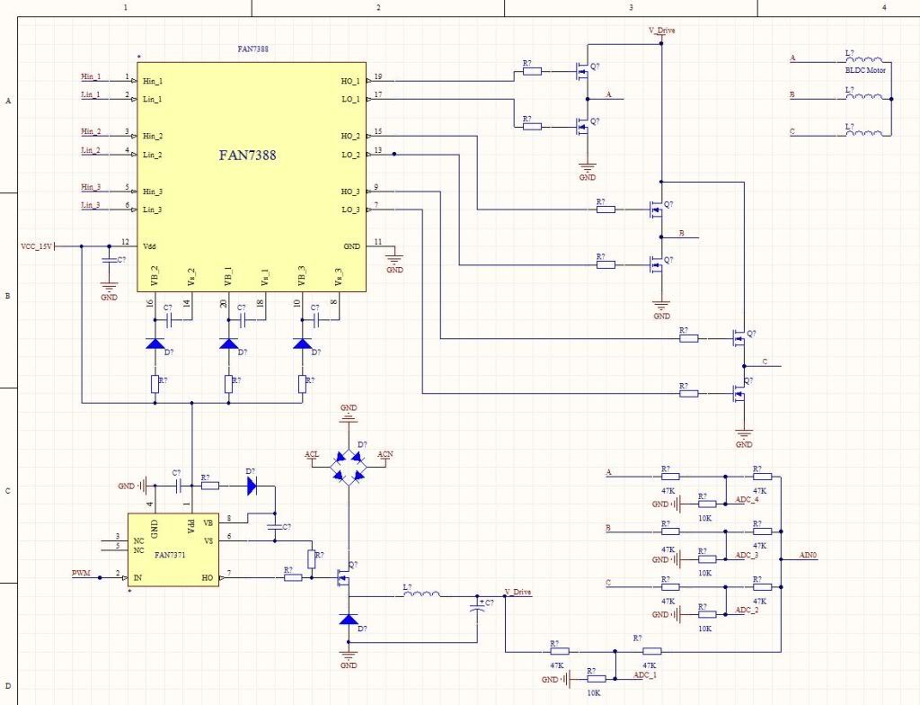
My thoughts are currently to use the Buck Converter as a current/voltage limiter for the BLDC driver section. I am thinking a 20kHz to 50kHz PWM in the Buck Converter should be enough to respond to any reasonable demands the BLDC Driver might have. Unlike the RC-ESC's I plan to use fixed (ie user selected) frequencies for the BLDC and monitor the feedback for slippage; if the slippage > x%, then increase the duty cycle in the Buck Converter until enough current/voltage is supplied to reduce the slippage to a predefined amount. While the circuit is almost identical to the previously posted schematic of the Tower Hobbies 25A-ESC, the firmware will be fundamentally different. A lot depends on how accurate the "sensor-less" sensors are. The addition of a shaft sensor may be required.
It is highly probably that more than one Buck converter will be required to supply anything even close to the 50+ Amps some of these motors require, but I'll cross that bridge when I get to it. Like I said, this schematic is more of an outline than a design. I have also not decided definitely on MOSFETS or IGBTs. I have two motors on order, a 2.2kW & an 800W:
https://www.hobbyking.com/hobbyking/...dProduct=14408
&
https://www.hobbyking.com/hobbyking/...dProduct=14734
They should be here in a week or two. I will begin by playing with them and the driver stage. My goal is to get the driver stage & the firmware up and running w/o letting the smoke out of a large pile of semiconductors, LOL. Hopefully over the next few months I will learn enough about these motors and controlling them to post a tested/working schematic//firmware.
Just for the record, this is an intellectual pursuit; I have no plans to attempt to sell anything; In fact, I expect this project will cost a couple thousand dollars and a ton of time, but it is a hobby, it is suppose to cost money, lol. I will post anything that works as open-source. If I get tired of letting the smoke out of semiconductors I will likely just give up on it, lol.
Fish
-
06-21-2011, 03:03 PM #48
Registered
- Join Date
- Apr 2009
- Posts
- 165
WOW!! Thats a little further than I was planning on going. Hats off to ya if you can pull it off though. I would still like to see the interface available to the super PID. I hope it moves forward.
Eric
-
06-21-2011, 03:54 PM #49
Registered
- Join Date
- Jan 2008
- Posts
- 853
@Fish : Are all RC BLDC motors wired in the Star configuration that you show? Are there any with Delta wiring? Does it matter for your driver?
Cheers!
-
06-22-2011, 02:14 AM #50
Registered
- Join Date
- Oct 2005
- Posts
- 2392
Thanks for the info Tskguy! Originally Posted by tskguy

 Actually if 256 steps is a "good" controller then that practically rules out PID control. Good PID control requires 10000 steps or so. With the 256 steps the "I" (integral) will hunt pretty badly, which will be compounded severely if the motor and load have a low inertia (low flywheel effect) so that means our target motor and worse still if the load is erratic, which a cutting tool definitely is!
I have done some preliminary research and it looks like we may be passing on this one, at least for now. It is important to us the SuperPID gives very high performance and very high reliability. In the case of a 3-phase brushless SuperPID that would now mean quite a lot of circuit complexity to achieve both those goals with a 50amp to 100amp motor! And that would be quite a high priced product the total setup would be in-line price wise with commercial VFD spindles which have a motor and collet etc all better optimised for the power and RPM.
Also Fish4Fun has (and is) investing time and effort into designing an open-source 3-phase brushless driver so we must respect that. I'm still interested in how this project goes and will keep an eye on his thread.
Sorry Paul if I sounded argumentative! Originally Posted by PaulRowntree
I was trying to express that there are 2 basic ways these motors can be operated;
1; PMAC (synchonous AC) where the speed is fixed because of a fixed drive frequency, so small changes in voltage, current load etc make no difference on RPM. RPM is determined solely by the fixed drive freq. The problem is how to determine the drive voltage and current, without being forced to run the thing like a stepper motor at full current all the time.
2; BLDC (brushless DC) where the speed is always determined by the motor itself (from sensor or phase) and the motor is driven from a fixed PWM voltage. Then RPM and current are both determined by load. So RPM control must be done closed loop based on sensing motor speed and increasing PWM voltage. This is how the BLDC controllers work including the RC "ESC" drives although the RC "ESC" drives are most likely NOT closed loop!
-
06-23-2011, 07:17 PM #51
Registered
- Join Date
- Mar 2007
- Posts
- 217
RomanLini,
I am exploring new territory, so please feel free to correct me when I am wrong; I am a hobbyist, not a professional. My current thought is to use a synchronous AC approach but use the feedback loop to determine voltage/current (This is a radical departure from RC BLDC "speed controls"). My thought is to build a constant 3-phase "drive" PWM based on motor speed = 3-phase frequency/Poles per Revolution. By measuring "slip" from phase to phase, the controller will adjust Duty cycle in the Buck Converter to raise/lower current/voltage. Obviously this approach is part of ALL commercial VFDs (regardless if the current limiting is handled in the drive portion or the supply portion of the design). While adding a rotor position sensor to the motor is certainly possible, it is my hope to use the feedback circuit favored by the RC ESCs. In either case, if a "delay" between the drive phase and the motor phase occurs, more power is required. Increasing the duty cycle in the Buck Converter should increase the voltage and current in the drive circuit. If the adjustment causes slip to fall back into the "acceptable slip range" then no further adjustment is needed. If the slip begins to approach Zero, then reducing the duty cycle in the Buck Converter until the slip increases to an "acceptable slip range" will reduce the power consumption.
Both the 800W and the 2.2kW motors I recieved have 12 stator coils and 16 magnets, so I assume this is a fairly common configuration. This implies 4 drive cycles per revolution or RPM/15 = drive cycles per second (Hz). So, for 30,000RPM we would need a drive frequency of 2kHz, 15,000RPM = 1kHz, 5,000RPM = 333Hz, 1500RPM = 100Hz and 150RPM = 10Hz. I can see both the low (<1500RPM) and the high (>15kRPM) being difficult to manage as the saturation of the stator cores and the inductance of the coils become difficult to predict/handle. It will be interesting to see where my theory "butts heads" with physics ;-)
What I really do not know is if I can design//build the buck converter portion of the design robust enough to handle the drive demands. I have "played" with the math, but not done a rigorous analysis. I plan to Spice the buck converter for up to 100A (these are welding currents! I cannot imagine these rather small motors consuming that much current!); my experience with Spice models and the "stock" components leads me to believe I will know a lot more when I watch the actual waveforms on a DSO.
Unlike commercial VFDs, I hope to come up with a design that is "modular" in nature. For instance, paralleling buck converters to increase amperage. Each buck converter PCB being designed for 10A to 30A depending on power devices // inductor cores, and "time sharing" the duty cycle between the stages (I have a really interesting idea for this, I will include it with the next schematic). For instance, 4 Buck Converter PCBs designed to handle up to 30A each, "time sharing" so that each PCB handles every 4th duty cycle. This would allow 100% "duty cycle" with each individual PCB only having a 25% duty cycle. Since precise volatge/current regulation is not mandatory, external 18V/12V/5V supplies can (and will) be used, and no "saftey" features will be included in the Buck Converter circuit, thus many complications of a commercial SMPS can be avoided. The only objective of the Buck Converter would be achieving the drive voltage/current, the PWM duty cycle will be determined by the Drive feedback loop, so essentially the Buck Converter circuit will be "pass/fail". If the Buck Converter fails to provide enough voltage/current, the fault will occur in the Driver circuit.
While I plan to use a discrete ATMega32, the project would port nicely to an Arduino, and the other portions of the circuit could all be built as "add-on-boards". An Arduino @ $30 + a Motor Driver Board @ ~$75 and "Buck Converter Boards" @ ~$75 each would make a fairly cheap ESC for these motors. Of course it is a lot easier to say a board will be ~$75 than it is to build one for that, lol. The cost on the driver board will be primarily in the power semi-conductors and heat sinks while the cost in the Buck Converter will largely be dictated by the Inductor. While I don't intend to make anything to sell, I want to keep the DIY price in the "reasonable range" (how much the final product costs me will depend on where I start counting, lol).
Anyway, still a few weeks away from any actual "testing", (though the motors arrived yesterday, way ahead of anticipated arrival date). I am going to have fun with these motors no matter what :-)
Fish
-
06-25-2011, 07:17 AM #52
Registered
- Join Date
- Oct 2005
- Posts
- 2392
Fish4Fun, I don't envy you this is an ambitious project. Designing a 2kW electronic motor controller can make pro's nervous... Even just getting industrial quality connectors for 100 amps! There's a big difference in "hobby racing 100 amps" and "professional industrial 100 amps".
Your proposed method sounds good, I would have chosen a similar system at least as a first option to be explored. If you can maintain RPM under micro control and measure motor load using the phase angle sensing reliably it should be workable. Some motors have hall sensors built in, I guess your don't? You might wan't to get some VFD data/schematics to see how they have handled certain issues on pro VFD drives.
I would work slowly and don't worry about the finished design at first, so all the prototyping should be done for testing. You will need a really hefty DC supply and 3 half-bridge drivers.
Then I would characterise the motors, as I'm really sure the motor won't do 2kW at low speeds. Do you have power/RPM charts supplied with the motors? Shaft power is a function of *RPM and you are talking a VERY wide RPM range, so if it makes 2kW at 30000 RPM it might only make 0.01kW shaft power at 150 RPM (200 times slower!) even given similar torques.
It would be nice to have a test setup to be able to set (PWM) current and voltage separately, then run the motor at any desired speed and test it's torque. You can do a lot with the manufacturers charts for the motor ie; power/RPM or torque/RPM and efficiency/RPM, but a dyno really is the best way to go.
-
06-28-2011, 11:21 PM #53
Registered
- Join Date
- Mar 2007
- Posts
- 217
Originally Posted by RomanLini
LOL, the good news is I don't HAVE to make this work, it is a hobby pursuit, and hence, in theory, I should enjoy the project :-) I plan on starting "simple" with the 800W motor and a 12V deep cycle car battery for a power supply. I should learn a lot about RPM and actual currents/voltages w/o having much to worry with except the H-Bridges and uController.
These are Chinese motors designed for the RC hobby industry, not a whole lot of technical data on them, lol.
I don't have a "real dyno", but my thought was to start with simple "no load" tests and then when the bugs are worked out, drive a second motor as an "alternator" and vary the electrical load on the driven motor to alter the load. The results will be "relative" rather than absolute, but this should be good enough for my purposes and very similar to a spindle motor under actual load.
I strongly suspect the actual power/efficiency of the motors will diminish with RPM and at some "threshold" RPM there to be insufficient power to do anything useful; I just don't have any idea what that threshold RPM will be. In theory, increasing the current through the coils will increase the magnetic field and thus increase the torque. The problem with this "theory" is it does not take the stator's magnetic properties into account; that is on the low RPM end, once the stator approaches "saturation", more current simply adds heat, and on the high end, at some RPM the inductance of the stator will require increasing the voltage beyond the H-Bridge's capabilities.
Further reading on "sensing the un-energized phase" seems to hold some promise for an effective feed-back loop. The method employs using a voltage comparator (typically built into the uController) to sense when the un-energized phase "peaks" (rather than attempting to poll an ADC). In the existing ESCs this is used to time the next "step", but in a synchronous design this same information could be used to regulate current. If the "peak" arrives late, more current should be applied, if the "peak" arrives early, the current should be decreased. Obviously there needs to be some current limits set so that the ESC has an "upper current limit" to protect the motor.
I have a new DSO on the way, so testing should begin sooner rather than later :-) I plan to use the FAN7388 and irg4pc50k IGBTs for the later testing, but for now I have some HIP4082s in DIP packages and a bunch of power mosfets in various current/voltage ratings, so i will start with the 800W motor and fairly low voltage/modest power and work my way "up" from there. I have been thinking on the AVR firmware, and I will get that started while I wait on the scope to get here. Sadly while I am very familiar with AVR ASM, C is not really a strong suit for me, so I will likely write the firmware directly in ASM which will make the firmware a bit more difficult for many to read/modify. There is already some pretty good C code based firmware available, modifying it for my proposed circuit will likely be easier for many. Ultimately my goal would be to make all variables (frequency, voltage, current, slip, PWM, Direction etc, etc) user configurable via a PC front-end, but for the breadboard tests I will likely hard-code//hard wire for the specific motor.
Thanks for your input!
Fish
-
06-29-2011, 06:58 PM #54
Registered
- Join Date
- Jul 2007
- Posts
- 177
A single cost estimation :
AC spindle with inverter and a very good ceramics hybrid duplex bearing
vs
DC BLDC + controller for several KW + DC Supply for several KW
+ hig cogging torque etc no programable safety functionality
Makes limited sense in my case!!!
HjWhy reach for speed, when you could have precision instead!!!
-
06-29-2011, 07:18 PM #55
Registered
- Join Date
- Dec 2008
- Posts
- 292
Hj
Valid points that have been discussed before, but what fun would it be if we didn't think outside the box occasionally.
Don
-
06-30-2011, 10:31 AM #56
Registered
- Join Date
- Oct 2005
- Posts
- 2392
Fish4fun, it's obvious you have done your homework and know what you are doing so I don't have a lot ot add.
Maybe on the dyno side, if you use a load DC motor (as a generator) that has a chart for efficiency vs RPM/current etc (generaly they run about 70% eff at higher loads) then you can more easily determine shaft power than if you used a 3 phase AC generator with no chart...
-
07-04-2011, 04:23 AM #57
Registered
- Join Date
- Nov 2008
- Posts
- 522
I did start my own tech thread on BLDC spindles here:
131369-diy_brushless_spindle
Fish4fun, the buck converter prior to the switcher might be a good idea! However, 50KHz is not appropriate for a high-current supply, and no Atmel/PIC can effectively manage it.
And here's why- in any inductor, we have cost and physical size issues. For a given size or cost, as we ask for higher inductance, the available current-carrying capacity decreases. Even if you have perfect cooling, magnetic saturation presents a hard limit for the inductor's max current.
And don't neglect the issues with allowing the current to ripple a lot in the inductor. The inductor's saturation current limit is there, you don't want to be anywhere near that, especially at higher temps. Saturation will be disastrous if the current approaches it at any point in the cycle. So, allowing ripple reduces the current-handling capability of the inductor because of the Isat limit, thus for a given cost, we HAVE to select a higher inductance to avoid ripple, which means a higher resistance winding and a lower saturation current.
But as freq increases, the inductance required to get the required smoothness goes down. Thus we can go with a smaller inductance but greater current-handling capability.
A lot of smooth switchers go for more like 500KHz. Some go into the MHz range, but switching losses in the transistor does become significant and the gate driving must be done very carefully (skillfully). Board layout becomes critical.
A microcontroller can generate clocks in the 500KHz range no problem. However, the granularity is a huge problem- with say a 10MHz system clock, there's only 20 steps between 0% and 100% duty.
And capacitance becomes a major issue. Honestly, the BLDC controllers you see for RC blatantly abuse capacitors. Those caps are rated for a few amps of ripple at best, so they can't do a lot of smoothing. It's not an issue of low capacitance, but high ESR. An 8mm dia can electrolytic, 100uf, low voltage, might be 0.030ohms resistance. When you're trying to step-down 10:1 by drawing 200A pulses to make an average of 20A on the output, the cap can't filter that. The resistance allows ripple far in excess of what the capacitance alone predicted would happen. The heating will rapidly cause the capacitor to exceed its meager operating temp range for an electrolytic.
And electrolytics have a reduced and unpredictable service life when run at high temps near their RMS ripple limit. What typically happens is the ESR gets worse with age- which only compounds the problem. Eventually they can't filter the voltage ripple effectively and a circuit which initially worked blows up.
Really, ceramic MLCC is the way to go- these have very, very low ESR. In fact, you will rarely find one with an ESR even specified. In they last few years they've been made larger, but they're still expensive in terms of $/uF for a given voltage. But higher PWM freq reduces the capacitance needed! Don't bother with tantalums- despite the "low ESR" tag, they're really not- for their physical size, they're better than a tiny, high ESR electrolytic. And there are a lot of caveats to their use- they're not all that reliable when run close to their voltage rating, esp at elevated temps. Due to ESR self-heating, that will come up!
-
07-04-2011, 05:29 AM #58
Registered
- Join Date
- Nov 2008
- Posts
- 522
What motor RPM do you want to target, and what is your intended source voltage? Originally Posted by Fish4Fun
-
07-04-2011, 04:15 PM #59
Registered
- Join Date
- Mar 2007
- Posts
- 217
MechanoMan,
Very nice summary of Buck Converter caveats! I have been a casual observer of the evolution of Buck Converters for a decade or two and nowhere have I seen such sage pointers to real-world design collected all in one place! Most of what I know about Buck Converters has been gleaned from various App notes which tend to highlight a particular product's contribution to a circuit while assuming the reader is intimately familiar with all other aspects of SMPS design, which, in my case was never a valid assumption. If you have any suggestions for further reading I would truly appreciate guidance. Areas where I am particularly weak include real-world understanding of active and reactive component selection; that is, it is quite "easy" to model a Buck Converter using "ideal" SPICE models for the switch, inductor, diode and capacitor; however, as you point out, "ideal" components are not readily available! I am not asking you to take me to raise, just if you have any off-the-cuff suggestions for "further reading".
As far as placing a Buck Converter ahead of the BLDC driver...I am currently hoping to be able to avoid that. Perhaps you can give me your thoughts on the viability of a driver using rectified line voltage PWMed directly to the stator coils. The obvious advantages being reduced system complexity/component count/cost, and the obvious problem being variable stator properties from one motor to the next. Many of the application notes on BLDC drivers I have read suggest 180Vdc to 400Vdc supplies; however, I am 100% certain these app notes were NOT tailored for the BLDC motors readily available from the RC market.
As for the AVR family of uControllers and my choice of the ATMega32 being inadequate; I chose the AT32 as a starting place simply because I have a large repository of code and a familiarity with them and I assumed ~20Mhz was "plenty of processing power" for the task. Obviously you feel I should reconsider. I am fairly familiar with 8051 architecture, and MicroChip offers a series of 8051 based BLDC-PWM optimized controllers in the 50Mhz range, is this more what you had in mind, or should I be looking into DSPs/FPGAs? (I have been looking for a project to explore FPGAs for a couple of years :-), but nothing I have done thus far has really justified the learning curve). I will likely continue my initial testing with the AT32, but if I need to be reading/learning about a more robust processor I would like to do that in parallel with my testing rather than reaching a road block with the AT32 and then starting over.
Switching speeds > 50kHz....hrmmm. From reading I know 100kHz to 500kHz is "out there", but I have simply assumed that the switches would be difficult/expensive to source (not to mention drive!). Most of what I have read (again, App Notes) has highlighted designs in the 50kHz and lower frequency range. In a precursury hunt for an appropriate switch, I am considering the irg4pc50k from International Rectifier. Following are the typical switching characteristics:
Td(on) = 38nS
Tr = 34nS
Td(off) = 160nS (240nS MAX)
Tf = 79nS (120nS MAX)
Eon = .49mJ
Eoff = .68mJ
Ets = 1.12mJ (1.4mJ MAX)
My THOUGHTS were to set the minimum duty pulse to 10X (Td(on) + Tr + Td(off) + Tf) ==> 432nS * 10 = 4.32uS. Assuming duty cycle = 10% to 90% of the switching period, this implies a ~23KhZ (43.2uS) PWM frequency, but these thoughts are NOT based on experience or intimate knowledge of switching techniques, but rather based on my own assumptions. I suppose it might be valid to vary PWM frequency with duty cycle; that is, as power demand increases, decrease the "off time" as I increase the "on time". This approach might "max out" @ a 75% duty cycle of 12.96uS "on" and 4.32uS "off" for a maximum PWM frequency of 57.8kHz (17.28uS). For 100kHz operation @ 75% duty cycle it would take a 7.5uS "on" time and only a 2.5uS "off" time, but the device power dissipation from switching alone would be 1.4mJ * 100,000 = 140W, barely within the device limit of 200W @ 25C (and this dissipation does not include load based dissipation). I cannot imagine this device being suitable for anywhere near 500kHz operation.
Hrmmm, the numbers are SLIGHTLY better if one assumes that each H-Bridge will be "idle" for 33% of the time, but even then I would think 100kHz is pretty close if not beyond this device's capabilities, or perhaps I have missed some fundamental parameters? If you have any suggestions for a more suitable switch, or if I am NOT thinking along the right lines, PLEASE let me know. I don't mind letting the smoke out of components, but it is not a goal ;-)
As a side note, as previously stated, I will begin my drive testing with a low voltage/high current battery source. When (if) I get the firmware/circuit to function properly (that is, I get the motors to turn, lol) I will migrate toward higher voltage supplies. I do not expect to test any line driven circuits for a few months (and that is based optimistically on low voltage success), so there is plenty of time; besides, this is as much an intellectual pursuit as it is a quest for a product.
Fish
-
07-04-2011, 04:56 PM #60
Registered
- Join Date
- Mar 2007
- Posts
- 217
Initial testing will be with a 12V deep cycle marine battery (I have them on hand, lol). I hope to limit collateral damage to the motors and components using a low voltage for initial testing. Originally Posted by MechanoMan
As far as RPM, for initial testing I want to document what the no-load RPM range is for 12V compared to the stated KV rating. I suspect the no-load RPM to max out fairly close to the KV rating because I suspect the KV rating is tied to the stator inductance and hence is Voltage limited, but tests are always better than theory in my world.
The ultimate goal of the pursuit would be to develop an open source line Voltage driver and a PC-Based application that "tunes" the driver to the motor based on a combination of user input and motor feedback. I would guess the upper RPM limit for the firmware/driver will likely be in the 30k to 60k range, but this is currently just a guess. This goal may prove too ambitious, but it is early in the project so optimism has not yet been checked by physics. My goal is NOT to design a spindle, but a driver capable of powering a BLDC motor for use on a spindle, with some data on specific BLDC motor performance. While I plan to start with a synchronous approach, I may well end up right back with a more conventional BLDC approach where voltage/current are adjusted independently of commutation and speed is averaged through a feed back loop.
I received my new DSO the other day, so as soon as I can get the firmware done I will breadboard a driver and begin testing, but please feel free to continue to point out errors in my thinking! (It is NOT too late to save the life of some innocent semiconductors!)
Fish

 Reply With Quote
Similar Threads
-
BLDC motor
By fraspelle in forum CNC Machine Related ElectronicsReplies: 8Last Post: 03-31-2020, 07:09 AM -
NM-145 BLDC motor problem
By Turbo442 in forum NovakonReplies: 4Last Post: 01-03-2014, 01:58 PM -
X2 BLDC Motor
By whitehedr in forum Benchtop MachinesReplies: 4Last Post: 11-11-2013, 05:53 AM
