


Hi all.....it's getting very exciting now.....for all those asking the whats and whys etc......if you'd ordered a machine a month go it would almost be on the water by now.....LOL.
Sky is right, the shipping cost is according to the package, but it's at the other end you have to allow for mostly, that is the Customs Brokerage fees to get it to your destination.
It does pay dividends to work out the package, as in the options and any peripherals you'll need, well before hand and try to include them in the one buy package to be included with the order to cut down on individual shipping costs.
If Sky has any contacts in the Customs Brokerage area in OZ that would be handy if a good deal could be made.
BTW, one question I wanted to ask, regarding the need for a Z axis zero device, or that little round box thingy that lights up when you touch the tool end on it to get your zero height.
Does this mean you need to zero all your cutters tools for their Z height etc to the zero device and store the info in the Mach3 file database somewhere?
What if the tools are all mounted in their own tool holders and placed in a holder on a steel table and each one individually zeroed to a fixed height with a dial indicator and a reference point?
I've seen this done many years ago before my CNC interest time and wondered why it was needed.
Is this the old way to do it or just another way?
I think it would be simple to make a block of steel with a taper to match your tool shank mounted on a steel plate and have a gauge block to set all your tools to the same height with a dial indicator.
Why or when would you need the touch and see the light block costing around $300?
I have designed a setting block with a plunger to activate a dial indicator that would set the tool to zero while in the spindle, but now don't think I would need it.
Surely if the tool was preset to zero off the mill there would be no need to jog the Z axis to get the tool point to touch the zero device?
I can imagine that with the SVM-0 with the basic spindle having an ER32 chuck on the end, the need to touch and get zero from a setting block would be necessary as you cannot have preset tooling in that set-up, but with removable tool holders this is not the case.....each one goes back in the same position.
If my reasoning is correct I need to make an ISO20 tool shank holder on a steel base with an indicator and gauge block etc.....this is much simpler than a zero setting block device.
On the other hand, would this zero setting block device only be necessary for when you have a high speed spindle with engraving cutters that are held in the ER 16 spindle and have to be zero set in situ?
I think I can see a need for both devices now.
Ian.
Results 681 to 700 of 3662
-
11-19-2013, 04:52 AM #681
 Member
- Join Date
- Sep 2006
- Posts
- 6463
-
11-19-2013, 01:08 PM #682
Gold Member
- Join Date
- Jun 2004
- Posts
- 6618
I am not sure when you might use that "light block". I don't use one. I use a piece of telephone book paper. I just rip off a page and step down until my zero tool hits it on top of my part. Then zero the DRO's and then all my tools in the Mach 3 tool table are referenced for this job.
I use TTS tooling and I start with my shortest tool. In this case it is a 3/16" end mill and it is tool #5. It is the same height as my tool #0. Everything is referenced off either of these tools.
I turn each tool upside down in a Tormach collet holder and then using the height gauge, measure the difference between tool #5 and the tool I am working on now.
Say tool #8. On the Mach 3 Offsets page on the right, I type in the #8 tool number and hit enter. Then below that I record the difference of the two tools. Lets say .25" and hit enter again.
Below that is the tool size or diameter. Then below this is a button to Save tool offsets. Hit that and visually look at your tool table. You can give each tool a nickname here as well. Then you can go back to the main Mach 3 screen when you are done.
I suggest shutting Mach 3 down at this point so all those tool table inputs are saved as default.
Then reload Mach 3 and get busy.
Oh yeah. Reach over and hit the off button on that digital height gauge now to save the battery.
PS.
Once completed with everything, copy the entire Mach 3 folder to another hard drive as a backup. That can really save your hide down the road.Lee
-
11-20-2013, 03:50 AM #683
Member
- Join Date
- Sep 2006
- Posts
- 6463
Hi Lee, thanks for that info.....I assume each tool gets it's own height reference/offset and is entered into the Mach3 database.
Would the paper page "feeler gauge" method be slow as you would have to creep down to the zero setting when jogging the head down to prevent a hard hit on the part.........the light or dial indicator block has a spring loaded spindle that can cushion a hit and show when it made contact........the light would come on as soon as it touched and the dial indicator one would show the needle moving as soon as the tool point touched it.
I think that with the LED light block, the Z axis automatically retracts when the controller senses the step that made contact and records the zero point, etc.
The dial indicator block would have to be a manual watch it and record method as no electronic feedback to the controller could be had with a moving needle.
I think the cushioning effect of the light block would be necessary when you have a carbide engraving cutter with a fine point....one hard touch and it's history......LOL.
Re-reading your post, I get the idea that you zero at least one tool to the surface of the job for getting a starting point to do a cut etc, same as you would when manual milling and touching the work piece with the cutter to get zero, and all other tools are related to that one by their offsets.
As I understand it, this zeroing then is for the particular job being done.....all other jobs require re-zeroing the first tool again and the others are related to that by their offsets so Mach 3 always knows where each tool point will be ....on that particular job.
Does this also mean that without a tool setter table and tool shank clamp with height vernier or gauge blocks, each tool would have to be individually zeroed on the job or a LED light block, whatever, and re-recorded in the Mach3 database every time you do a single tool change or job change?
Without a tool setting table with a shank clamp etc to secure the tool shank for tool changing, an LED light block would be invaluable to the zero setting if a single tool is changed in the middle of a job.
I suppose the top of the vice fixed jaw could be used as the touch down point for zeroing and all tools offset in relation to that, which in the middle of a job where a tool is changed the vice jaw would make a stable fixed zero point in all cases for all cutters and you'll know that anything below zero will carve the vice up.
With this info on the cards, Sky could add an economical LED tool zero setting block to his web site inventory for all those that wanted one and couldn't find one on EBAY.
The same could be said for a tool setting table........just the tool shank holder body by itself, tapped on the bottom for two SHCS to hold it on the steel base, for ISO 20, 30 and possibly R8 that would make holding and fixing the tool in the holder easy, and the buyer only needs to buy a piece of CRS steel plate to mount the holder on.
The holder body is the hard part as it has to have an accurate taper in the bore and a means to secure the shank in place without the draw bar or shank retention system, to suit the buyers tooling shanks, so.... being made and supplied by the "experts" is highly desirable.
Ian.
-
11-20-2013, 11:55 AM #684
Gold Member
- Join Date
- Jun 2004
- Posts
- 6618
Okay.
My #0 tool is just a steel rod. It isn't a cutter. No chance of knocking off teeth there.
When you jog in Mach 3, there is a slow jog and a fast jog. Hold down the shift key and the appropriate arrow key and it moves fast. Release the shift key and you have slow incremental or step or very precise slow movements with each key press.
I have mine set to .01". I think the page is around .0025" thick. It just seems to work well for our needs. Of course our tolerances are not that high, ergo the not so accurate paper trick.
In Mach 3, just hit the tab key anytime and you can reset the jog speed to whatever you wish. Done? Hit the tab key again and it's entered.
Once tool zero is referenced to the top of your part for that job, then your whole tool corral is referenced there as well as long as the offsets have been recorded in the Mach 3 Tool Table. I reference only once per job or part type. Then I reference these parts to the vise to get the correct starting point on all the blanks that I am machining. If I am machining all the same thickness blanks all day, the Z Zero only has to be referenced the very first time in the Morning and no longer needed throughout the day.
All this is providing that all tools have the same type of tool holder. I can't use TTS and then switch to an R8 tool that has no set point for height control and then back to TTS without re-zeroing with the #0 tool.
All this sounds complicated kinda, but once the tool table is set, it takes me less than about 20 to 30 seconds to zero Z. Sometimes quicker. Not much time at all in the scheme of things.
An auto tool setter like you mention is useful. No doubt about that. It just makes things more complicated initially. Also allows another point of failure and maintenance due to extra electronics and tweaking of the auto tool setting script needed. Of course, Sky could work those out ahead of time.
Everything is dependent upon just how accurate you want to be. An extremely accurate auto tool setter is not cheap.Lee
-
11-20-2013, 03:11 PM #685
Member
- Join Date
- May 2009
- Posts
- 154
I use Tormach tooling, and I do offline tool measurement similar to what LeeWay describes by using a granite plate and a height gauge.
My tool #0 is an old Mitutoyo digital indicator in a Tormach holder . That makes a setup that looks basically like this (that's Tormach's indicator and holder as one package).
Attachment 209456
I set the height gauge to a fixed height which puts just a little bit of preload on the indicator, and zero the indicator at that height. That fixed height is what goes into the tool table.
To touch off Z height for a part, I change to tool #0 in my control software (LinuxCNC in my case, but it should be similar in Mach3). Then I manually jog Z down until the indicator touches the part and increment in by .001" until it reads zero. I then click "touch off Z" in the software and set the Z height to 0. From that point the rest of my tool heights are referenced properly.
It's a similar concept to using a fixed bar or an LED edge finder, but I think it's safer because it's not a rigid point of contact. I also think it's more accurate and takes the guesswork out versus techniques like using thin paper.
-
11-20-2013, 04:29 PM #686
Member
- Join Date
- Sep 2006
- Posts
- 6463
Hi all, I understand the process now that I can relate to the need for zero points for all in the tool register.....just very new to me and the learning is totally different to manual milling.
The zero setting blocks I found on EBAY UK were of 3 similar but different designs, and all used a dial indicator to read in Imperial or Metric, and ranged in price form about A$80 to A$180.
The first one at $106 uses imperial increments, an indicator on the side with .25" travel with markings at .001", and is 4" high, using 1 2 3 blocks to set the gauge to 4" exactly from the table surface.
The next one at A$150 is a 50mm aluminium alloy cube, with a spring loaded button on top, acting on a dial indicator on the side to give 2.8mm travel with .01mm increments set for zero by placing a parallel across two small buttons on top and the plunger and zeroing the indicator dial to read 50mm exactly.
The last one at A$180 is a 50mm stainless steel cube with a plunger on top, set for zero by a small dial on the side that activates a pin inside to set the plunger to 50mm exactly by turning the dial of the indicator.......2.8mm travel in .01mm increments.
I've seen an LED type at our local machinery dealers with a zero adjust for the touch point, but it cost A$233....on special.
I think I might go for the A$150 one as I like the setting to zero by a parallel across the top method.
I'll have to investigate on getting the setting bench made up as it simplifies tool management, I think.
So, the zero setting gauge is used to set the initial zero point at say 50mm from the table surface which then gives you the known zero point to the top of the vice jaw and also the offsets for all the other tools in the register, and then you can set the zero of the top of the job surface......jobs heights will vary but the #0 tool and all other tools related to it will always be at a zero point with their offsets known to Mach3 etc.
Ian.
-
11-20-2013, 04:56 PM #687
Gold Member
- Join Date
- Jun 2004
- Posts
- 6618
Like I said, it adds more levels of complication and mathematics to the setup. My vise jaws are not a known location for anything. This means when I do make a mistake and have to resurface the jaw tops and then remill a step for part holding, that I haven't fundamentally changed anything. The zero point is always the top of the material.
When you do jobs that have different heights, it's easy to loose track and get the math wrong if using the jaw height as zero.
When you zero to the top of the part, no math needed.
You can also use an inexpensive touch plate that you hold on top of the part. It's known thickness can be input into script to auto tool zero. It could have a plug in the head of the mill or somewhere to make it easily removable and not susceptible to chips and coolant.Lee
-
11-21-2013, 03:14 AM #688
Member
- Join Date
- Sep 2006
- Posts
- 6463
Hi Lee, that's logical, the top of the job would always be your starting point.....now why would you want to set a zero down at 50mm from the table with the zero setting block?
Am I right in saying that in the middle of a job if a tool is damaged and needs replacing, not having the original uncut surface to zero on and not having a tool setting bench, then the tool setter block is the only zero that is constant for all jobs and relative to all the other preset tools?
So, if I have a setting bench, I don't need a tool setting block, but would I need a setting block when I use a high speed engraving spindle where the cutter is mounted directly in a collet in the spindle end and I wanted to use different shaped cutters?
The mill I'm getting has an ISO20 spindle with removable tooling that can be set on the tool setting bench if I make/get one, but if I don't then I will need a tool setting block........also, as I am getting a high speed spindle for the mill too that has a fixed ER20 collet chuck on the end, then I will need the setting block for engraving cutter changes.
I appreciate all your guidance......please correct me if I'm wrong in my assumptions as I'm waiting to get the mill to learn the CNC ropes etc.
-
11-21-2013, 04:06 AM #689
Gold Member
- Join Date
- Apr 2009
- Posts
- 5516
You could also get a combination probe/toolsetter. You could even make one as there are plans floating around. Then you can also use as a center finder, edge finder, or as a 3D scanner... Originally Posted by handlewanker

-
11-21-2013, 01:58 PM #690
Gold Member
- Join Date
- Jun 2004
- Posts
- 6618
What I was suggesting and explaining was the most basic of setups for production work. It is the simplest and least complicated way to have known tools do a 2.5 D job.
When you start doing 3D jobs, that is when you need another point for zero and the table mounted setter will probably shine. I am not adverse to using a probe. I just think for most applications, it over complicates things.
Even if a part needs surfacing, that is usually done in a separate op. That is if both sides need to be flattened.
That is how I have to do it because my facemill is an R8 and not a known height.
Speaking about face mills, mine is 2.5" and the tool setter thing on the table would not work for it. It's cutters are on the outer edges. This is why facing is a separate op. At least for me and my machines.Lee
-
11-21-2013, 02:39 PM #691
Gold Member
- Join Date
- Apr 2009
- Posts
- 5516
What I was suggesting was using Mach3 to measure the tool offsets; while it can be done between operations, it can also be done beforehand and all offsets recorded. Originally Posted by LeeWay
-
11-21-2013, 02:47 PM #692
Gold Member
- Join Date
- Jun 2004
- Posts
- 6618
Right. But not when you need a tool that cannot be input into the tool table or when the surface (Zero) is removed. There are any number of things that can cause you to loose position. Lost steps, broken tool, etc.. If replacing a tool offline and setting a new offset for it, (rare that you get two tools sitting in the same position at the same depth) offline is the best way to handle this. Just update the tool table and revert back to before the breakage and either run from here or set next line. Flawless actually.
PS. That can be done with a probe too. I've just never done that and I'm not too sure how that would do in the middle of a job in Mach 3.Lee
-
11-22-2013, 04:02 AM #693
Member
- Join Date
- Sep 2006
- Posts
- 6463
Hi Lee, am I correct in thinking that all tools are initially set to a #0 tool as the master zero point and are directly related to it?
Then when you have the job in the vice you reset the #0 tool or blank probe to the new zero, the top of the job, knowing that all other tools will also be related to the new zero, so Mach3 knows where every tool point is?
When you load your tools to their tool holders in a setting bench with a height gauge etc, do you then record the different cutter heights in the mach3 tool register?
Does this mean that, if you have a tool setting bench, when you break a cutter and have to replace it, when the height is set in the bench with a height gauge this is then used to reset the register for that tool no in the register?
This is like driving a car by reading the driving manual first before you get behind the wheel....LOL.....it can only get better when I get my paws on the machine.
Ian.
-
11-22-2013, 02:26 PM #694
Gold Member
- Join Date
- Jun 2004
- Posts
- 6618
That is all correct.
Lee
-
11-23-2013, 04:13 PM #695
Member
- Join Date
- Sep 2006
- Posts
- 6463
Hi, By George I think I've got it....LOL.
Thanks for your patience.
Ian.
-
11-25-2013, 07:50 PM #696
Registered

- Join Date
- Jul 2011
- Posts
- 441
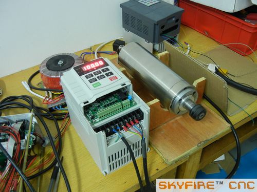
Hi guys, I really got too busy these days so have not posted much recently. Just let your guys know that everything is under going now
a picture of high speed spindle and VFD testing.
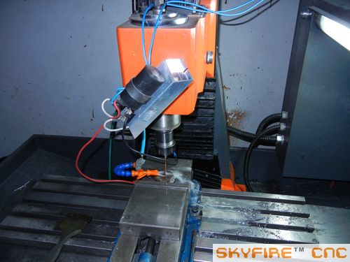
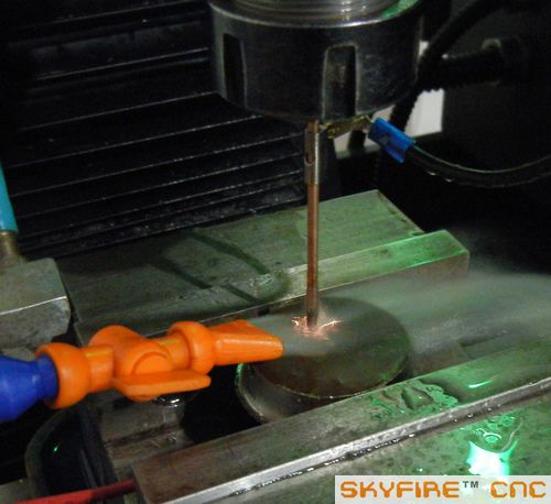
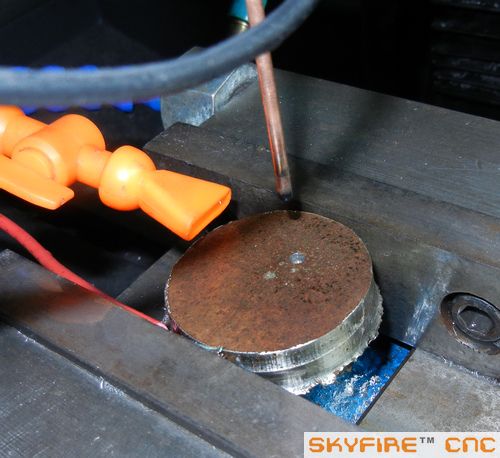
Here I post several pictures of a small test with SVM-2 prototype. Since sometimes workers may break screw taps in the hole and can not pick out any more.. So I may need an EDM device to burn the broken screw taps to save the workpieces.
I made a very simple RC electric spark generator to do this. It's realy a temperary device so i just hung it on the machine head now. A 60VAC transformer powered it up( not in the pictures). I clamped a copper rod with a plastic tube inside the ER chuck to make the copper pole isolated to the machine body. And the workpiece with the whole machine body were linked to another pole of the device. It worked finally but very slow and the spark is not stable because the EDM circuit is so shabby without close loop control. So sometimes the circuit maybe shorcut so must be controled manually..
This is just a simple test to consider, maybe we can have another optional EDM accessory for SVM machines. at least I proved it will work..LOL
I have no experience to DIY EDM before.. I'm sure some guys did. Can we find a simple, better EDM generator solution to do this?
 www.skyfirecnc.com
Email: [email protected]; Skype: skyfirecnc
-
11-25-2013, 09:44 PM #697
Gold Member
- Join Date
- Apr 2009
- Posts
- 5516
Nice spindle! Originally Posted by Skyfire
-
11-26-2013, 06:39 AM #698
Member
- Join Date
- Sep 2006
- Posts
- 6463
Hi Sky, if you're doing commercial work and tapping is involved, the chances are you will break a tap eventually.
I would "invest" in a good EDM for that purpose as it not only saves time but gives a better job too.
There is an EDM DIY book put out by Ben Fleming, called The EDM How To Book, with a circuit board available too, but as the technology is pretty much established now the book is mostly for DIY users who want to create a few parts from hardened materials etc.
It's basically a transformer with a timed capacitor charge/discharge circuit and shows how to make the unit using modified cut down draw slides for the mechanism and a small DC geared motor and leadscrew to move the slide.
Ian.
-
11-26-2013, 07:37 PM #699
Registered
- Join Date
- Jul 2011
- Posts
- 441
Hi Louie, actually the spindle belongs to you! lol..
Handle, The main purpose of the EDM part is not just a tool on my facility.. I have another equipment called HESD actually can be used as an EDM too---I guess. haha.
I'm just thinking that maybe EDM is a possible accessory to expand the machine usage. EDM is not a new toy at all, just I have not touched it before. I'm sure some guys will be much more experienced and will be happy to DIY this for SVM machines..lol
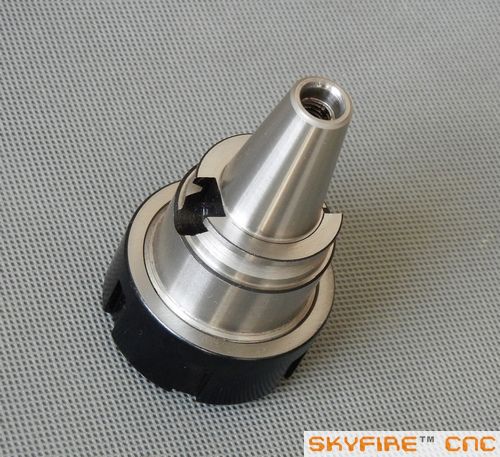
And, I have a good picture for you now.. your 80mm ISO20 spindle part.. actually I prepared several sets for customer option. Yours are under assembling now.
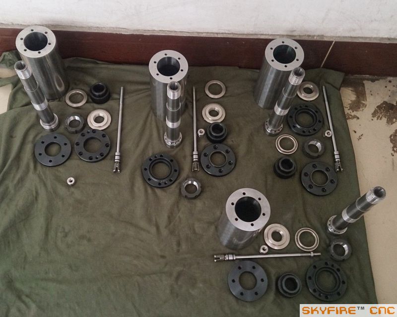
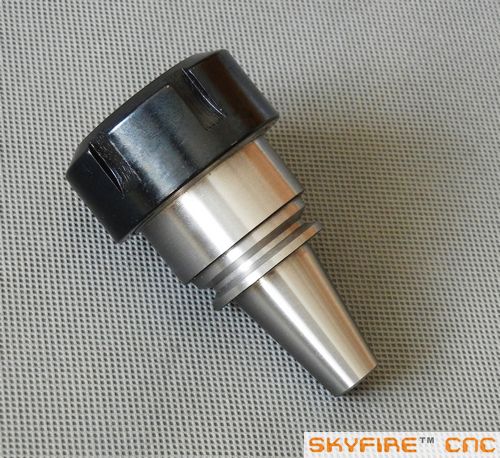
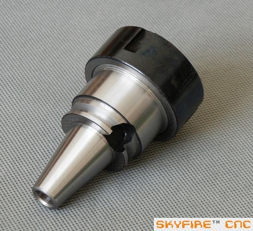
And this is your ISO20-ER32 tool holders. a small man with a big head I think...lol. Unfortunatelly they can't grind the surface as the BT30 one .. because it's too mall special order and they don't have the tooling to hold the ISO20-ER32 onto their polishing machine---actually, I can understand any factory will not be happy to do this . I hope I can order over 100pcs next
")
Actually I have some R8 QTC parts finished now too. but the QTC system is not full completed so I will introduce this later.
And I didn't take many picture during the machine building progress because I need time to do many things..So will just show some key progress here so not reapeating former details. Thanks guys. :cheers:www.skyfirecnc.com
Email: [email protected]; Skype: skyfirecnc
-
11-27-2013, 02:20 AM #700
Member
- Join Date
- Sep 2006
- Posts
- 6463
Hi Sky......."a small man and a big head"......LOL, very well put.
That's good news on the ISO20 spindle.
One important acquisition for the SVM series would be a decent mill vice.
I have in mind a toolmakers type vice with a 125mm wide jaw for the SVM-0, as this has quite a low profile and with the pull down feature of the moving vice jaw it would do the job very well.
Ian.

Similar Threads
-
Show us your machine stands
By OHLEMANNR in forum Benchtop MachinesReplies: 7Last Post: 05-05-2013, 03:19 AM -
a machine design (pics) from beginning to end
By blurrycustoms in forum Vertical Mill, Lathe Project LogReplies: 42Last Post: 04-25-2013, 02:36 AM -
dry build or glue from the beginning?
By Ezra in forum Joes CNC Model 2006Replies: 2Last Post: 10-29-2010, 04:44 AM -
Newcastle: Beginning of build plan
By pippin88 in forum Australia, New Zealand Club HouseReplies: 7Last Post: 09-16-2010, 10:22 AM -
Beginning to build my Z-axis.
By zonk2 in forum DIY CNC Router Table MachinesReplies: 0Last Post: 12-23-2008, 06:17 AM
