


What does a 1.1kw BLDC motor and driver set cost?
Results 801 to 820 of 3662
-
01-09-2014, 09:55 PM #801
 Registered
- Join Date
- Mar 2004
- Posts
- 1306
Regards,
Mark
-
01-11-2014, 08:54 PM #802
Registered

- Join Date
- Jul 2011
- Posts
- 441
Thanks guys!
The formal USB controller BOB will be ready in 2-3 days.. PCB is on the way to me now..lol
I finally got the passed ISO20-80 spindle units now... Only 4pcs passed the QC! I think it will be smoother next from the first experience of this new stuff to my spindle family..lol
I will take some pictures tomorrow to show it. And next work will measure and design the spacer to make the spindle motor position fit the ISO20-80 spindle height next.www.skyfirecnc.com
Email: [email protected]; Skype: skyfirecnc
-
01-11-2014, 08:56 PM #803
Registered
- Join Date
- Jul 2011
- Posts
- 441
Hi RotarySMP, I've PM you the price. I'm not very sure about delivery yet before know your exact address. Please send me email if you have intention. Thanks! Originally Posted by RotarySMP
 www.skyfirecnc.com
Email: [email protected]; Skype: skyfirecnc
-
01-12-2014, 07:22 AM #804
Member
- Join Date
- Sep 2006
- Posts
- 6463
Hi Sky, that's good news, glad to see you are being very particular.......every day is a day closer to delivery. Originally Posted by Skyfire
Ian.
-
01-13-2014, 06:36 PM #805
Registered
- Join Date
- Jul 2011
- Posts
- 441
Hi, here is the ISO20-80 spindle assembled onto handle's SVM-0.
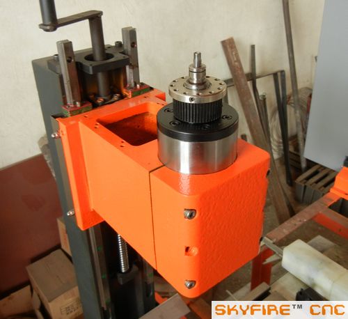
ISO20 taper
with the ISO20-ER32 tool hoder
I measured the pulley to head top distance about 45mm. So next we will need to make 2 spacer blocks to make the motor pulley at the same height.www.skyfirecnc.com
Email: [email protected]; Skype: skyfirecnc
-
01-13-2014, 06:56 PM #806
Registered
- Join Date
- Jul 2011
- Posts
- 441
Here is a message to Tkamsker because your message box is full

I think you mean the BT30 spindle? the toolchang force is 1000kgf.
Yes, I sell the piston together with the BT30 spindle unit. It's not a heavy part.
Best Regards,
Defengwww.skyfirecnc.com
Email: [email protected]; Skype: skyfirecnc
-
01-13-2014, 08:59 PM #807
Member
- Join Date
- Feb 2008
- Posts
- 521
Whilst this may be a pre-production or development unit it doesn't look good having the Z linear rail trucks covered in orange paint like the unit has been painted by a 5 year old! People / purchasers remember stuff like this!
-
01-13-2014, 09:12 PM #808
Registered
- Join Date
- Jul 2011
- Posts
- 441
Hi kawazuki, you are right that the the linears don't look good because paint and dust on them now. Everything has oil on surface will look like this after a while. For the specially ordered machines we can't finish them soon so it will gather dust because of longger assembling term. But we will clean up all the details before sealing and final pack up. Believe me I'm showing the real conditions along the building but not just make everything beautiful for pictures. That's the real conditions in the factory workroom. I'm sure we will get stuff better and organized when everything get standard next. Cheers~ Originally Posted by kawazuki
www.skyfirecnc.com
Email: [email protected]; Skype: skyfirecnc
-
01-13-2014, 09:21 PM #809
Registered
- Join Date
- Jul 2011
- Posts
- 441
Here is the formal USB controller BOB that just been welded and tested OK. I added 2 relays for VFD forward/reverse control. Some VFDs have different COM pin and GND pin for F/R control and +10V analog voltage. So for universal compatible of all VFDs, these 2 relays are very necessary. I also add 2 LEDs to show the power status of the extra DC power and DC/DC power output.
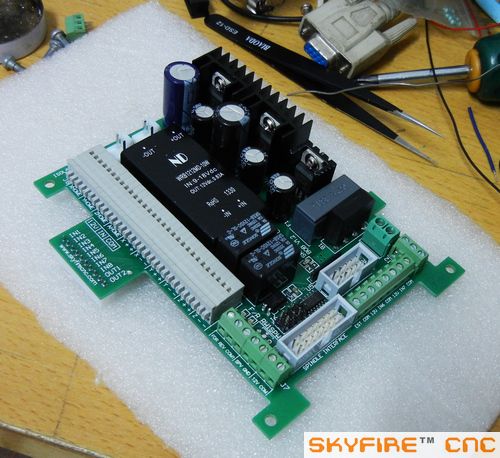
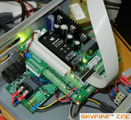
And the new stored 800W tranformer for SVM-2 machines. Very heavy, beautiful one that I'm satisfied with.
 www.skyfirecnc.com
Email: [email protected]; Skype: skyfirecnc
-
01-14-2014, 06:01 AM #810
Member
- Join Date
- Sep 2006
- Posts
- 6463
Hi Sky, that is exactly as I thought it would be like. Originally Posted by Skyfire
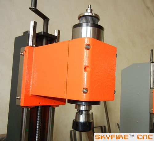
This "stick out" of the spindle at the top of the head is a big advantage to me as I have designed a power drawbar (actually two different designs) and now it will be an easy way to attach it to the spindle body diam.
It's starting to look so good I can almost smell the paint.
I would have to say that I'm extremely impressed by the quality of the electronic assemblies and the very professional appearance of them too.
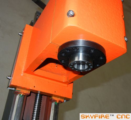
I see in the photos that there are only 4 bolts fitted to hold the split half of the head on..........will the other two holes in the middle be filled in and painted over as they are not really needed for the clamping, or are they already drilled and tapped to eventually have 2 more screws fitted?
If they're not drilled and tapped all the way through then dummy plugs will do the job too, but mainly for appearance.
I have another question.....now that the ISO20 milling spindle is fitted and in the position that I anticipate it will be used at, what is the actual distance between the bottom of the ER32 chuck nut face and the table with the head at the top of the column?
The next question is.....what is the pitch of the holes in the Z axis linear rails?........I have a plan that needs to know what the pitch is for a possible extension to the linear rails to gain more Z height, but that is only an idea on paper at the moment, and at best it would only be to get more height for tool changes like drilling etc and not for machining.
With the present dimensions and a job in the vice, if I need the height I can move the table to one side to get the tool off the job, so I'll cross that bridge when I come to it.
Louie favoured a spacer at the column bottom, but I prefer to consider just extending the top travel a bit if needed......the hole pitch looks to be about 75 to 100mm.
It's a pipe dream at the moment, but could be a consideration if the need arises to gain more Z height.
Ian.
-
01-14-2014, 08:07 AM #811
Junior Member
- Join Date
- Jun 2007
- Posts
- 3891
all linear rails (except tiny or massive ones) have a 60mm hole pitch. its a universal standard.
moving the rails up will probably not work well. youd also need to move the ball screw, motor mount, etc. the top of the travel will also be not useful other than for a tool change, as youll have no support. so youd lose travel in the end, unless you bought a new longer ball screw as well. at that point, you might as well get a whole new longer travel column.
column spacer is the better choice all around.
about the head: you don't want to tighten screws in the middle holes, it may cause stress - warp. theres no material there touching the spindle. you could just put screws in, but not tighten them.
-
01-14-2014, 08:02 PM #812
Member
- Join Date
- Sep 2006
- Posts
- 6463
Hi Avno, Yes I understand the middle screws do not actually do any clamping, but as they are probably already there the holes need to appear to be used.
The column mod I mentioned was just a passing thought as it may not need to come to that.
I doodled up an idea on my graphics pad that had the Z axis linear rails extended further up above the column for about 75mm to gain extra height if needed.
This is not to do machining, but purely as a means to get the head up higher to ease tool changes that someone mentioned may be difficult with the ISO20 spindle, ER32 chuck and a vice on the table with a job in it......I like to be prepared for any possible eventuality BEFORE they become problems.
At the same time the ballscrew would have to be longer too and that means relocating the upper ballscrew mounting block to a higher position on the column.......a bit of machining to give a flat area at the top of the column and a spacer block would allow this to happen.
This also means the stepper motor must be mounted higher, and to do this all it needs is a bracket shaped like a Z that bolts to the top of the column and also the back of the linear rails to give them some support.
At this moment there is a flat plate bolted to the top of the column to mount the stepper motor on, and the proposed Z shaped bracket will just replace it to bring the stepper motor mount higher.
The top of the Z shaped bracket would then be higher to mount the stepper motor on.
It's a relatively simple solution and does not interfere with the dynamics of the column structure as it exists as it does not have to resist any forces exerted by the cutter.
The total cost would be for two longer linear rails, longer by one hole pitch and a longer ballscrew........the bracket being made to measure etc.
This is only a design concept that I thought of in case the height below the spindle became insufficient as some have noted.
There is no way that I would want to fit a column spacer to raise the column, even though it APPEARS to be a simple solution, the purpose of getting more height is purely for more clearance if needed.
Anyone who has dealt with mechanical things will know that if you add a short spacer to a rigid column you decrease the overall rigidity, and that is the very last thing you'd want to do.
Ian.
-
01-15-2014, 02:53 AM #813
Member
- Join Date
- Sep 2006
- Posts
- 6463
Hi Avno, just had another look at the column pics from an earlier post and what I'm suggesting is now totally a simple retrofit, IE, no machining required at all.
In the attached pic you can see the top of the column has been machined flat and drilled and tapped for the stepper mounting plate.
So.....all you need to gain extra height is to have linear rails longer by one set of holes, a longer ballscrew (+ 60mm?) and a Z shaped bracket.......nothing else, and that includes NO machining of the column to take mounting block for the longer ballscrew.
The face of the Z shaped bracket supports the back of the longer rails and also forms a mounting face at it's lowest part for the ballscrew.
Lastly, the stepper motor just mounts on the top of the extended top face of the bracket as it follows the same shape as the existing mounting plate forward of the rails.
I think this could be an option for more height as it's so simple and requires no re-machining in any quarter, and so could be a retrofit kit for that purpose.
Perhaps Sky can add some comments as it does not "re-engineer" his planned layout to any degree that cannot be returned to the original format.
I'll attach a photo from a previous post showing the area I mentioned so that it is clear as to where the "modification" can take place.
It is possible that the cable at the right side of the head to the control box would need to be lengthened if the mod was attempted.
This is still just a concept, but as it has huge possibilities I think it will be feasible.
The Z shaped bracket is like an angle plate with an added top piece for the stepper mount, so it's a simple design to fabricate from 20mm thick steel plate welded together and machined flat and square where needed.
Ian.
-
01-15-2014, 03:37 AM #814
Member
- Join Date
- Sep 2006
- Posts
- 6463
Hi, here's a sketch of the bracket to show how simple the mod could be.
It only has to add support to the extended rails and stepper motor when the head is at the top of the column, and as no machining in that mode is envisaged there will be no deflection problems from cutter forces.
Ian.
-
01-15-2014, 03:48 AM #815
Junior Member
- Join Date
- Jun 2007
- Posts
- 3891
the ball screw is sat well behind the plane of the rails, not in front. what you are proposing is a very complex part to make precise. hope you know how to scrape.
as with your other mod... there is a reason why every other engineering company in the world would add a column spacer instead.
-
01-15-2014, 10:01 AM #816
Member
- Join Date
- Sep 2006
- Posts
- 6463
Hi.......scraping???.....who scrapes when you can machine the part.
Scraping is only for final fitting and finishing........done enough of that in my time.
As far as the ball screw centre line allignment is concerned, it just follows the existing bracket hole centre but a bit higher up, and the distance from the face of the linear rails and the centre of the ballscrew is already established.....you'd only have to reproduce it on the bracket but higher up which is as easy as falling off a log.
There is nothing rocket science about machining a 90 degree angle bracket as shown in the sketch.....mills do it all the time.
The bracket will add support (even though it's not needed) to the increased length of the linear rails above the column, but I did not design the bracket purely for that purpose, but it is a bonus none the less to have some extra support in that area.
With the mod, the head will be able to rise above it's present position and still be accurately positioned on the linear slides, and all it does is sit there while tools are changed, especially long drills, reamers and boring bars etc.
I don't know if I'll ever need to go down that path but I want to be prepared just in case.
If you are aware of any specific problem that would arise from such a mod it would be interesting to know about.
Ian.
-
01-15-2014, 11:17 AM #817
Junior Member
- Join Date
- Jun 2007
- Posts
- 3891
when you extend the rails, will they just float in the air then? your drawing suggests they would mount to it, which is impossible with that design.
making this bracket precise enough for mounting a ball screw which must be in line with the rails, it's original position on the column, square to the top of the column is not that easy. possible, yes, but not easy. if you get it off by even .0005", the screw and rails will bind at the top.
the main point (as always) is that you are taking a tried and true design, and rejecting it for one that will likely land you with a non working machine for many months if it ever works at all.
skyfire has taken great care (more than most factories) to ensure this machine is precise and aligned, and your going to chuck that out the window without any gain.
just use the machine, then worry about the mods later
-
01-15-2014, 04:46 PM #818
Member
- Join Date
- Sep 2006
- Posts
- 6463
Hi, that's just a matter of opinion at best.
If you studied the sketch you will see it is merely like an angle plate with another projection on top for the stepper mount.
The base of the angle plate like bracket is bolted to the column top, just like the existing stepper motor mounting plate, and the vertical part of the bracket will be bolted to the back of the rails.......simple if you study the sketch......this gives the rails support.
If that is a difficult design to envisage, better leave it to me to decide if I want to go down that path.
There are people out there who are capable of machining things to certain limits.....I've been doing that for the last 60 years, the last 10 of which I was in retirement.
BTW, nothing in this mill design is being rejected, just a proposal to modify certain aspects for MY benefit to increase it's capability.
I thought I'd post the proposal in case someone was also interested in the aspect of more Z travel and could add some constructive in fill......two or more heads being better than one etc.
So far Avno, all you have done is add derogatory comments........for that matter I don't like the spacer option either, even though I have one on my Ajax mill, but like the Bridgeport the Ajax weighs almost 1-1/2 tons, so the spacer is in a different category altogether.
This proposal is purely hypothetical and needs to be looked at in detail with hands on appreciation of the area concerned.
It will be some time, if ever, that I will contemplate any idea of a modification, but it's a distinct possibility.
With this design I see it as wearing a tall hat to gain extra height as opposed to wearing high heel boots.
Ian.
-
01-15-2014, 07:58 PM #819
Member
- Join Date
- Jan 2005
- Posts
- 15362
handlewanker
What you may do at some time, will work just fine, the Haas minmill has 4" of unsupported rail above the column, & can even be used for light milling if someone had to use it up there, the top bearing is just over 4" long, so the bearing is still supported at the bottom when it is at max travel, this is not the only machine that has unsupported rails, those that do, it is mostly just used to gain extra clearance for tools,work EtcMactec54
-
01-15-2014, 09:00 PM #820
Junior Member
- Join Date
- Jun 2007
- Posts
- 3891
Originally Posted by handlewanker
your drawing - if it were to support the rails - is placing them BEHIND the plane of the ball screw mount. in reality they are almost 2 inches in FRONT. thus your design will not be a simple z bracket, but a complex 3d part.
its doable, but far more complex than you are thinking it will be.

Similar Threads
-
Show us your machine stands
By OHLEMANNR in forum Benchtop MachinesReplies: 7Last Post: 05-05-2013, 03:19 AM -
a machine design (pics) from beginning to end
By blurrycustoms in forum Vertical Mill, Lathe Project LogReplies: 42Last Post: 04-25-2013, 02:36 AM -
dry build or glue from the beginning?
By Ezra in forum Joes CNC Model 2006Replies: 2Last Post: 10-29-2010, 04:44 AM -
Newcastle: Beginning of build plan
By pippin88 in forum Australia, New Zealand Club HouseReplies: 7Last Post: 09-16-2010, 10:22 AM -
Beginning to build my Z-axis.
By zonk2 in forum DIY CNC Router Table MachinesReplies: 0Last Post: 12-23-2008, 06:17 AM
