


Indeed, you are very, very right, Doug.
Even more than I thought. So far I didn't thread lock or pin anything on the carriage, not even the studs as instructed in the manual, perhaps for several reasons:
- Curiousity: just to see what would happen and what would come loose first.
- Maintainability: I just wanted to be able to take things apart again and fix/replace parts withouth having to go to the oven.
- Lazyness: I could have drilled at least the component holes for pins, but I didn't.
Anyways, all that caught up very quickly with me, so here is the progress so far.
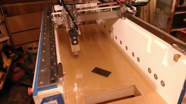
I cut and screwed down the t-rail sections across the entire length of the machine:
WP_20131018_004 by mkloberg, on Flickr
In terms of chipload and cutting forces, MDF seems to be easy to work with, so I ended up cutting all the tiles for the spoilboard for the machine, on the machine itself!
While doing that, I found out that there seems to be a backlash on the x-axis of about 0.008". I don't know if that makes sense yet, but I have a theory where that comes from:
The teeth in the x pulley are a tiny bit wider than the XL belt teeth really are.
I did several tests involving the machining camera coming from both directions and when working with backlash feature in Mach3, the settings that worked the sweetest were "Backlash distance in units (X): 0.008, Backlash Speed of Max: 100%".
I'm curious to see what everyone's opinion is on that, because most folks don't use the backlash feature of Mach3 I hear. For me so far, it completely eliminated the problem.
Anyways, after these tests, I felt confident enough to load a sheet of MDF and cut the remaining spoilboard tiles.
That went really well, including the profile, the rabbets and the pocket holes on the other side, all cut by the machine itself.
WP_20131020_001 by mkloberg, on Flickr
The only thing left at this point was to distribute the spoilboard tiles along the base and drill the holes in the centers of the pocket holes to mount the tiles to the spoilboard base plate.
I did that with the machine itself also, using two different toolpaths. One to drill a core hole through each tile and into the base. Then a second path to open up the hole in each tile to allow the screw to go through clear.
Getting a little bit worried that I might pull up one of these tiles while drilling, I made a set of holddown bars with a hole at each end that would fit into the outer t-tracks.
While cutting these, I ended up calling them 'monkey bars' because they are a shortcut to clamp something like this properly for drilling.
Having the monkey bars holding down all tiles in the bed, the machine drilled the core holes and the clearance holes in two passes.
WP_20131020_005 by mkloberg, on Flickr
This went great, and I was able to bolt all the tiles down without a problem. Throughout the three sections, everything seemed to be reasonably flat, adhering to the epoxy base level.
Finally, a good looking machining surface to work with / to clamp stuff down on, yay! :-)
Eager to try out something more complicated, I found an example on the net that was a small plate with a chinese dragon and a weaved border around it, so I decided to make that a test cut.
Roughing with a .25 Endmill and finish with a 3mm ballnose.
WP_20131021_011 by mkloberg, on Flickr
Keep in mind that this is still with fully extended Z-axis, very high up. Having the spoilboard assembly in there now brought the base up a little higher, but there's still a lot of z-flex lever in play.
During the cut, especially on the right side, the machine started to stutter, indicating that there is something more than flex going on at the beginning stages of a problem I would find out about pretty soon...
For now, this very first piece off the CNC was more than I expected - with the Z still hanging that far down.
WP_20131021_016 by mkloberg, on Flickr
The next day, my GF asked me about doing some curved flat boards for a trial product they had in mind. In woodworking, this is when you cut shapes out of 3/4 boards and assemble+glue them sideways.
This little project was about 6 of those shapes that had holes in them to make a small wavy board for seeing if the machine could do it.
While making the toolpaths, I kept thinking about the still hovering task to pin and threadlock the parts on the gantry, because things could come apart!
And they did... I guess these wavy shapes and the addition of the hardness of real wood instead of just MDF triggered a chain reaction in the carriage for things to give away.
Half way throught the second part, everything started to shake so violently that I hit the e-stop button to prevent further damage:
WP_20131023_004 by mkloberg, on Flickr
With the endmill still stuck in the board, I started to clean up and get ready to take the gantry apart for pinning and thread locking (long overdue).
This is what that first part looked like by the way, it's giving some clues on what gave a way first and what went on during the cut.
WP_20131023_005 by mkloberg, on Flickr
After looking at this and checking all the bearings for tightness, I found that the lower front bearings on the y-axis were completely loose.
Everyting else was still tight.
Looking at the front bearing blocks (part #14) revealed that these two blocks have shifted under the load.
I'll have to pin these in as a first fix, but there isn't much real estate to drive the pins through on this part.
Next was a complete strip-down of the carriage, fortunately I was able to take it off the y without taking that apart too, utilizing the hole in the base - taking out the z-axis first.
All that took less than 20 minutes, yay :-)
WP_20131024_001 by mkloberg, on Flickr
Looking at the problem some more in Sketchup and where to place the pin holes into part #14 to prevent that from happening, I found some beefy places for the pins:
WP_20131024_002 by mkloberg, on Flickr
Everything is in pieces right now, probably a good time to thread lock the studs I didn't do yet too and examine some more spots where pins can help for stability.
WP_20131024_005 by mkloberg, on Flickr
--
Mac
Thread: Build thread: Mac's Momus X2S
Results 81 to 100 of 166
-
10-25-2013, 04:07 AM #81
 Registered
- Join Date
- Mar 2013
- Posts
- 209
-
10-25-2013, 03:45 PM #82
Registered
- Join Date
- Jul 2013
- Posts
- 38
Fantastic work, Mac.
Don't fear thread locker. If you use the blue Loctite, it is removable without heat. Where I work, we don't assemble a single bolt without it, unless it is used on a plastic part. If we have to disassemble things, it takes a bit more torque to loosen the hardware, but not so much that it hurts anything.
BTW, we don't use it on plastic parts, because the ammonia gas it give off when curing causes the plastic to become brittle. Before I knew about this, I once used Loctite on a plastic handle on a torque wrench. The next time I went to use it, the handle had hundreds of tiny cracks all through it, and fell apart when I picked it up.No signature I would write will fit on only two lines.
-
10-26-2013, 02:31 AM #83
Registered
- Join Date
- Mar 2013
- Posts
- 209
Thank you for sharing your experience with the blue thread locker. Especially the advice to keep it off plastic parts, that is really good to know.
I don't have all that much experience with the blue stuff, but I did find a 10ml bottle in one of my shop cabinets which was leftover from a riding lawnmower breakdown a few years ago. This is MxLoc 42, the stuff that Harbor Freight sells for $2.99 a bottle - all the writing on it is blue and the stuff itself is blue, so I hope this is about equivalent to Loctite Blue, which I don't have on hand right now. I'm going to try it and lock anything that's not supposed to get the 271 permanent locker that Bob recommends in the manual.
Thanks again & stay tuned... :-)
-
10-29-2013, 06:57 AM #84
Registered
- Join Date
- Mar 2013
- Posts
- 209
Well, the teardown of the carriage went good - I used plenty of the blue thread locker and roll pinned all the parts that could possibly move in place.
Here's how that went... :
First of all, I was very concerned about how to take things apart again if I had to, so all the holes had to go all the way through.
If you install a roll pin, you want a way to get it back out. In my apprenticeship, we used tapered pins that have a hole with threads inside, so you can screw a threaded rod into the pin and knock it back out the same way it went in. With the roll pins, you can't do that.
Tapered pins require a reamer to prepare the hole, in this application I didn't want to go all the way down that route, but I still wanted to be able to take things apart if needed, so that meant drilling through wherever a pin goes.
After taking the carriage apart, I thought about this a little bit. Why would both bearing blocks (#14) want to slip on me?
Making the parts shine really nice was probably counter productive in this case, that eliminated any grip they would have had, so I decided to rough up the mating surfaces a little bit with 100 grid sandpaper, doing a criss cross pattern.

WP_20131025_001 by mkloberg, on Flickr

WP_20131025_004 by mkloberg, on Flickr
The next step was to align the bearing blocks with the carriage blocks (#16 & #17) carefully and bolt them together in their final position. I just layed them flat on the granite marking surface and tightened one screw to hole the assembly in place.
I sort of forgot about that the washer would cover up the hole when assembled when trying to locate the pin hole in Sketchup, so I had to alternate.

WP_20131025_007 by mkloberg, on Flickr
Let me tell you, driving these pins in at zero clearance ain't easy. I had to whack them pretty hard with the flat side of a ball point hammer and busted several screws acting as push rods.
Finally they went in all the way through the material (roll pins are 1.5" long)

WP_20131025_010 by mkloberg, on Flickr
To lock the studs back into place, I added blue thread locking liquid on the ends of the studs:

WP_20131026_001 by mkloberg, on Flickr
That will never come apart or move around again, yay!

WP_20131026_002 by mkloberg, on Flickr
Having that process down, I did the same thing to the part 15, which is the upper bearing for the z and the lower z bearing block as well (14).
While at it, I started thinking about racking on the carriage.
This machine already has the solid carriage plate mod with the spacers, but I wanted to make sure it won't rack at all down the road and placed four pins all the way through the plate, the spacers and through parts 12 and 13, the two rear carriage blocks.
Some creative clamping on the drill press was required to drill through all that in one piece while lined up and assembled...

WP_20131026_004 by mkloberg, on Flickr
Putting everything back together, with the pins in place:

WP_20131026_008 by mkloberg, on Flickr

WP_20131026_009 by mkloberg, on Flickr
And putting it back on the gantry.
WP_20131026_011 by mkloberg, on Flickr
As a little side story, I had another idea on how to get rid of the corner ridges in the epoxy pour using a card scraper while trying to flatten out the little vulcanoes that the holes for mounting the spoilboard created earlier, now that it's off.
Worked great, look at the shaddow to the right of this picture, a little card scraping too the rigde right off and the epoxy surface is now perfectly flat.
Why didn't I think of that earlier, lol?

WP_20131026_013 by mkloberg, on Flickr
Next was to go through all the alignment steps again and finally to put the tramming bar back into place.
Surprisingly, that went pretty quick to get the router motor back to where it needed to be. A few things needed to be tighted up, until the bar turned true all the way around.

WP_20131026_014 by mkloberg, on Flickr
A thing to note is that I'm still not using any shims, anywhere - I'm 100% sure that this can be done on any Momus without shims in your router mount, by just playing the set screws in the bearings to minutely tilt the z-axis in the diretion you need it to be.
Putting the spoilboard tiles back in:

WP_20131027_001 by mkloberg, on Flickr
Trying to do the wavy curved board pieces again, which is what revealed all these problems in the first place.
Z-Axis is still over extended and I'm going slower now, about half. Instead of 180, now at 90 with 12,000RPM.
To my chip rate calculations, this will tax the 1/4 endmill a lot more and let it become hotter than it needs to be, but right now I can't do more without making it vibrate and stutter again.

WP_20131027_003 by mkloberg, on Flickr
It did stutter a few times, especially in the inside curves of the arcs but only on the final pass. Overall, the fix worked I think.
I was able to assemble all the slices by sticking 1/4" dowels through them, which was the original plan.

WP_20131027_004 by mkloberg, on Flickr

WP_20131029_003 by mkloberg, on Flickr
What is it, you may ask... :-)
Well, I just wanted to prove to my GF that this process was possible on the machine.
Eventually, these will be much longer and turn into designer style curved bookshelfs or walls for funky furniture, such as this:
http://cdn3.artboom.info/wp-content/...eaumont-10.jpg
Other trick doing this is to only drill half way through one of the slices, using it as the front piece, basically hiding the dowels that align the whole board.

WP_20131029_004 by mkloberg, on Flickr
As of late, I'm a bit concerend about my right x-axis rail, the rollers have minutely deformed it already to a point where it built up an extremely sharp upper edge.
I've gotten several hints from users of the forum and a few private messages also that indicated more and more to me that having all this hinge (yes, hinge, literally as in lever) on the four upper drive rollers to control the x flex of the gantry is not going to cut in the long run.
Perhaps, I should take the plunge and put in a slave x motor on the left side to stabilize its movements in the x direction.
Having seen how it performs, I'm almost ready for that now.
On the other hand, taking the still somewhat extreme z axis deflections out of the equation should be the next goal, by building a riser table insert.
What do you think?
Stay tuned,
Mac :-)
-
11-04-2013, 04:29 AM #85
Registered
- Join Date
- Mar 2013
- Posts
- 209
Hi guys,
just a quick update on the riser insert:
Just finished designing the thing, it's basically just a little box that sits on top of the base machining surface to raise the work area up to a point where the z-axis only has to extend by very little for cutting through a 3/4 to 1" work piece. There are through holes in the spoil boards to stick a socket down into the base to clamp the riser box onto the t-rails down below. I also designed it to have a vertical clamping face for the parts to come up from under the machine.
Lately, I've done some more research on how to make CNC dovetail boxes and hope this riser insert will make that finally possible, yay!
Here's the design, I'm going to cut the all rabbets, dadoes, mill the pocket holes and drill the through holes on the machine itself in the next few days...

2013-11-03 21_02_12-MomusX2 by mkloberg, on Flickr

2013-11-03 21_04_25-MomusX2 by mkloberg, on Flickr
Stay tuned,
Mac :-)
-
11-04-2013, 04:32 AM #86
Registered
- Join Date
- Jun 2009
- Posts
- 267
I've been following your progress Mac and you have done a most impressive job I must say! I've thoroughly enjoyed seeing your build come together. Looking forward to more!
Sent from my iPad using Tapatalk - now Free
-
11-06-2013, 03:27 AM #87
Registered
- Join Date
- Jul 2006
- Posts
- 102
I've been watching this thread for a while and I'm very impressed with the work you have done.. Well most of it.. That cutting board you made just doesn't look right to me.. I think with a little more tuning, and maybe that new riser platform, you should be able to get that flat. Originally Posted by Mac.CNC


-C
-
11-06-2013, 04:21 AM #88
Registered
- Join Date
- Mar 2013
- Posts
- 209
Thank you :-) I know exactly what you mean, a little more fiddling and it should be all good and flat soon ;-))) That got me laughing pretty good, awesome!
I'm really looking forward to making truly flat butcher boards finally, heehe...
Tonight, I cut all the members for the new riser platform on the table saw, and some extra blanks for the spoilboard tiles which I'm still missing in the base.

WP_20131105_002 by mkloberg, on Flickr
From here it's just making toolpaths and running the parts.
I really hope the new riser will get me up and running at this point :-)
--
Stay tuned,
Mac
-
11-23-2013, 05:54 AM #89
Registered
- Join Date
- Mar 2013
- Posts
- 209
Hello again,
sorry for no updates lately, I've been traveling a bit for work so there wasn't much time to work on the machine but now I'm back on it.
To make more accurate cuts, I've decided to build a riser that will offset the work surface up, in terms of height.
Here's how that went:
Cutting the top and bottom plates on the machine itself:

WP_20131107_003 by mkloberg, on Flickr

WP_20131107_009 by mkloberg, on Flickr
Machining the ribs with the holes for the box:

WP_20131108_002 by mkloberg, on Flickr
First dry assembly:

WP_20131109_007 by mkloberg, on Flickr
After what happened last time to make the spoil tiles in terms of time (these are identical to the ones that went in the base), I figured that it might be easier to cut the rabbets on the table saw instead of the machine.

WP_20131110_008 by mkloberg, on Flickr
A big focus was to keep the top cutting surface of the box at an absolue 90deg angle in reference to the front of it, as this would transfer into any items made on this riser box.
Tip here, if you can't see the angle, shine a light at whatever measuring device you are using in from the the back...

WP_20131110_011 by mkloberg, on Flickr
It's coming together.

WP_20131110_010 by mkloberg, on Flickr
All the pocket and through holes, were milled on the machine itself.
Honestly, making the toolpaths took me so long, I would have probably been quicker on the drill press with this...

WP_20131118_003 by mkloberg, on Flickr
All holes drilled and everything fastened, it's all in place now to do some serious CNC damage, lol.

WP_20131121_003 by mkloberg, on Flickr
Well, long story short: I think this machine is now finished. I still need to build the cover, but having it in use so extensively lately, I really like to be able to be able to access it from the front for tool changes and clamping the workpieces.
I should probably rethink the cover thing again before building it.
Dust collection is still way up on the project menu, by now I've gotten into a habbit to wipe the rails with WD40 almost every day. That does seem to keep them clean and keep the buildup of sawdust crap on the rollers in check.
Anyways, now that the riser was built, it seemed to be a good oportunity to try some horizontal CNC'ing.
I picked one of the more respectful levels of woodworking to see if the machine would be able to do it: DoveTail Jointing
I've ordered a variety of dovetail bits the other day, but they are no here yet, so I tried to make due with a 14deg 1/2' bit that came out of a set from Sears.
Trying to figure this out on the computer and making a nice, evenly spaced joint toolpath, I ended up with just making the pins for now. Making the receiving board will be a project for another day.
Anyways, here are some pics on the pins for the doetail joint pins, I think that turned out pretty good:

WP_20131121_005 by mkloberg, on Flickr

WP_20131122_002 by mkloberg, on Flickr

WP_20131122_007 by mkloberg, on Flickr

WP_20131122_008 by mkloberg, on Flickr
Next up is to try to mill the mating part for this joint.
Happy CNC'in,
Mac
-
11-28-2013, 05:30 AM #90
Registered
- Join Date
- Mar 2013
- Posts
- 209
Just a quick update on the dovetailing endeavour.
Inbetween, I cut some stepped hold down clamps out of plywood:

WP_20131123_006 by mkloberg, on Flickr
I had no idea how much math and trial and error is involved in this, but I think I have a decent grip on it now.
The first thing that had to be done was to provide some stops for the workpieces to be aligned on the vertical surface.
I figured, to keep these aligned with the cutting bit to just make some angular stops out of MDF, with some slots to clamp them in either direction and to get the workholding clamps near the workpiece.

WP_20131124_001 by mkloberg, on Flickr

WP_20131124_002 by mkloberg, on Flickr
These can slide in and out, to accomodate any size material going into the machine vertically. I then tried to cut the v-shaped dovetails with a dovetail bit.

WP_20131127_003 by mkloberg, on Flickr
Trust me, that looks a lot easier than it was. I probably went through a whole 8' board cut into little test pieces until I had a toolpath that would actually work. The beauty is that it's now repeatable, lol. (as in CNC :-)

WP_20131127_008 by mkloberg, on Flickr
There was no way to make this 100% accurate on this machine and the type of wood I was using (paint grade, not planed, on purpose), so I let the pins and the tails stand proud by about 0.015" to be able to sand them off once assembled and that worked out pretty good after making about four of these with different settings to arrive at that conclusion.
Looked and feeled pretty good as far as I can tell for a prototype.
The point was to make a CNC box carcas on the machine using dovetail joints.
It's a 5x5 test box, to make a 12x12 drawer box won't be any different.
Total CNC cutting time without counting cutting the blanks on the table saw was 25 minutes, but I think I can make that even faster by optimizing the pin toolpath a little bit.

WP_20131127_007 by mkloberg, on Flickr
There's still some tearout that I tried to combat with a very slow feedrate, but this is low grade white pine. I'd guess in a hardwood or something more dense, that wouldn't even happen.
So far, I'm very satisfied with the machine, but there's lots more to do.
The brush skirts, hoses and other hardware I ordered the other day came today, so it's probably a good time to start designing the dust collection shoe/system.
What has been intriguing me lately for fun, I thought about carving a 24x15" height elevation map of the Alps (topo-map) around Bavaria in Germany for my step dad as a Christmas present, so you might see some pictures on that soon (currently trying to find GIS data in that area to come up with the model).
Stay tuned & happy CNC'ing,
Mac
-
11-28-2013, 02:10 PM #91
Registered
- Join Date
- Dec 2012
- Posts
- 38
Mac, based on my (somewhat limited) experience with my dovetail jig, you are going to need a backer board for what ever becomes the exit side for your dovetail bit. Even with that, I have not yet discovered a technique to prevent tear out on the entry side.
I am curious how you programmed the tool path for cutting the pins and tails - this looks like a much easier (less labor) way to cut dovetails than my dovetail jig.If it weren't for the last minute nothing would ever get done.
Jim
-
11-29-2013, 09:43 AM #92
Registered
- Join Date
- Mar 2013
- Posts
- 209
Wow, that's good inspiration right there for a better cnc jig setup. Honestly, I've never cut dovetails with a router before, only by hand traditionally, clearing with the saw then using carving tools (as in chisels). The amount of tearout I got using it this way even at slowing the federate way down (to 5), blew out fibers of the wood.
It's not so bad on the entry of the router bit, obviously but when it comes out, it's pretty bad even on the CNC.
I was so excited that it actually worked and came together, I haven't even thought about using a backer board yet, so thank you for that - I'll try that soon.
For your question on how I generated the toolpaths, I can only say - don't try this at home, lol.
There is a lot of geometry involved to even lay this out in a way to make it come out right.
I'm using Sketchup and the CAM plugin, but had to go back into the generated G-Code file here and there to make it do what I wanted.

14DegDT0.5-Layout by mkloberg, on Flickr
This is looking at the joint from the end grain of the board(s) we're working with, the green box outlines the edges of the wood.
The box was made with two toolpaths:
Tails:
Super easy, just four straight passes with a dovetail bit, perpendicular to the material at the desired depth at a veeeerry slow feed rate (shown in blue)
This was cut with a 0.5" 14Deg dovetail router bit from a set from Sears.
Pins:
That wasn't so easy, what I did was basically cut an imaginary pocket (the insides of the black lines) on the end of the board.
You'll probably notice that the bounding box is bigger than the board itself and that the pins stick out of the left side of the board, because I needed to fool the cam software to think that there was more material to cut to get the toolpath I needed. This part was cut with a 0.25" endmill.
Long story short, I probably spent two full evenings to get this right, so unless you are planning to make 50 of these boxes in the near future (which I am, lol, got an order already), you might be better off sticking to your jig to cut dovetails. ;-)
It's a lot of time consuming work to calculate the toolpaths and setting up the machine, bit changes + edge finder, also clamping the workpiece takes a while - there are a lot of reclamping operations and resetting the z-axis each time a new piece is in the jig.
--
Mac
-
12-08-2013, 08:08 AM #93
Registered
- Join Date
- Mar 2013
- Posts
- 209
Sorry, I haven't posted much latetely - work has been busy and the machine kept throwing new challenges at me too.
NOthing that can't be solved though :-)
I 'think' that I have the dust collection thing under control now, but unfortunately the implementation is pretty specific to my extended machine.
I figured I'd show it anyways, perhaps you'll get some ideas for your Momus.
Mine doesn't have a cover yet, so the dust hose (full size, 4" is just dangling down on the machine from the ceiling).
I don't know about you, but the most ingenious dust collection shoe design I've found so far is made by KentCNC.
There's videos on YouTube about it and he sells these shoes at very reasonable prices.
I had to make a decision, and I was very close to just buy one from Kent considering the price for the acrylic glass, the magnets, the skirts and all the other hardware involved.
For my situation, the spacing between the spindle and the hose was a bit odd because there's a big electrical box on the spindle that needs the shoe to look a certain way, also - the neck on my spindle is 50mm in diameter and I didn't see that kind of thing in Kent's selection to make.
Long story short, I decided to make my own split shoe system, first with plywood and then later cutting the same thing out of acrylic glass, all reverse engineered from the KentCNC shoe, with some modifications.
Thanks again for KentCNC for coming up with this design in the first place, I hope you won't be mad at me for cutting my own - which might look strikingly similar to yours.
Here we go: In my design, there's four half inch rare earth magnets holding the skirt plate to the shoe (8 in total).
You can order these here: Magcraft NSN0586 1/2-Inch by 1/7-Inch by 1/8-Inch Rare Earth Ring Magnets, 12-Count - Amazon.com
Cutting the recesses for the magnets in 3/4 plywood as a prototype:

WP_20131130_004 by mkloberg, on Flickr
Here's the mounting plate and the skirt plate with the magnets installed:

WP_20131130_006 by mkloberg, on Flickr
I accidentially cut the magnet holes on the wrong side of the skirt plate, but that lend itself to a trick where I was able to just cut the same pocket holes into the spoil board, insert the magnets on both parts (the plate flipped over now) and let it orient itself on the magnets. Sort of like indexing pins in 3d cutting.
That made it easy to cut the magnet holes on the other side in the location they needed to be.

WP_20131130_002 by mkloberg, on Flickr
For the dust collection port, I found a $4 juction connector that I sliced a short piece off on the bandsaw - but just enough to leave a tiny lip on it.

WP_20131130_009 by mkloberg, on Flickr
That lip would then fit into a groove I routed around the underside of the shoe with a trim router and a cove bit.

WP_20131130_010 by mkloberg, on Flickr
To fasten the shoe to the spindle, a screw with a square nut acts as a clamping mechanism to tighten the plate around the hole for the spindle.
I've seen a few different ways to do this, but the way KentCNC solved this problem is awsome, so I followed that design in my version of the thing.

WP_20131130_011 by mkloberg, on Flickr
Once I had the shoe mounted on the spindle, it turned out to be really tight with the rest of the machine but worked out pretty good.
The Z-screw just bottoms out a few mm above the shoe and the back bearings just about kiss the shoe plate when the Z-axis does its homing/referencing routine.

WP_20131201_006 by mkloberg, on Flickr
The shoe from underneath. You'll see two groves to accept the brush skirt material from here.
A great piece of wisdom can be found in the youtube video from KentCNC. If you use a 3" outer brush skirt with a strong dust collection system, these long bristles will fold in and want to get sucked up into your hose.
Therefore it's a good idea to have a little seconday 1" skirt inside of all that to give the outer skirt more stability in doing its job.
Haha, you guessed it, that's what that inner groove is for :-)

WP_20131130_014 by mkloberg, on Flickr
The magnets work, the port works and I was able to attach a 4" hose to the shoe, suspending the hose from the ceiliing.
I had to adjust things a few times but eventually I could move around the entire envelope of the machine without causing any serious "snags" in the hose.

WP_20131201_008 by mkloberg, on Flickr
A good time to assemble it.

WP_20131130_008 by mkloberg, on Flickr

WP_20131202_002 by mkloberg, on Flickr
This is a great pic of the KentCNC idea of how to keep the 3" outer bristles from folding in by having an inner 1" skirt inside the shoe.

WP_20131201_012 by mkloberg, on Flickr
Next up was how to control the dust collector. And how to hook it up.
Mine is a cheapo 1hp Sears floor model, that I've had in the shop for a while. It takes a 4" hose and whenever it starts up, it makes the lights flickr.
Knowing this, I isolated it from the machine, so its way to turn on and off is by a pigtail and a plug that are hanging out of underneathe the machine with one lead controlled by a solid state relay.

WP_20131201_014 by mkloberg, on Flickr

WP_20131201_015 by mkloberg, on Flickr
I still have some issues with that relay, because no matter what I seem to do, all outputs go high for a second or two when I turn the machine on.
This is a C31 from CNC4PC which has an "Enable" input, but I'll probably need a Charge Pump board to control that input.
No biggie for now, but it's on the list.
Here's the shoe fully assembled:

WP_20131202_001 by mkloberg, on Flickr
The next problem I had was clamping, because of the dust shoe.
I've been using these high woodworking Incra clamps to hold stuff down and these would pretty much always collide with the dust shoe, in terms of height.
So I needed a system that was very flat. I've tried earlier to make my own clamping blocks out of plywood, but that didn't play out so well.
Those things:

WP_20131123_006 by mkloberg, on Flickr
The slightest amont of pressure on them and they would crack, snap in half, no good...
I got a little fed up with the clamping tactics and investigated how the PRO's do that on real mills.
There's a lot of really expensive accessories you can buy for CNC machines, but I also came across a clamping set that Harbor Freight sells.
You'll most likely won't find this in stores (I called them), so you'll have to get it online.
There's a bunch of variants of this set on Amazon also, for more money but shorter shipping, so pick one ;-)

WP_20131203_003 by mkloberg, on Flickr
Anyways, I got me two sets of these and combined them with the 1/4-20 hex hd cap screws that fit into the t-tracks with a big washer, lock washer ontop and a nut.
Now I can clamp anything without much effort and keep each job at an extremely low profile, yay :-)

WP_20131203_005 by mkloberg, on Flickr
Clean and easy:

WP_20131203_006 by mkloberg, on Flickr
That'll be firewood then, discarding the old plywood clamps:

WP_20131203_007 by mkloberg, on Flickr
Having all that in check, I decided to start carving 12x10 topo map I mentioned earlier.
This is my christmas present for my step dad and depicts the southern Bavarian region, called the "Allgaeu" - including all the mountains that he's been on already.
I can't really discuss the process on how to make these because some of the software to turn the geographical data taken by the Shuttle Mission in 2000 into a height elevation map for carving, but just wanted to show you that it works.
Early roughing with a 1/4 EM.

WP_20131206_004 by mkloberg, on Flickr
Finished roughing with the 1/4 EM:

WP_20131206_005 by mkloberg, on Flickr
Next was 1/8th ballnose roughting path to get into all the valleys and other pockets that the 1/4th mill missed earlier, before we can start a finish pass.
The software said this will take 10 hours, yikes... :-(

WP_20131207_003 by mkloberg, on Flickr
About half way through that job, the UPS man stopped by and delivered the 0.5" acrylic sheets that will make up the final dust shoe.
Just aboutt the same time, the prototype skirts got so low onto the workpiece that they buckled, so I stopped the whole thing and turned back onto the dust shoe.
Re-Cuttting it in acrylic, another idea was to make several with different brush lengths to accomodate whatever going on.

WP_20131207_004 by mkloberg, on Flickr
I just kept the topo thing clamped the way it was in the front of the machine and cut the parts for the dust collector i, n the back.
That way I can continue on the topo thing in the moring without having to re-orent the whole thing.
Lol, so here we are, 0.5" sheets of acrylic glass at hand but not knowing what we are doing.
I googled heavily on what feeds and speed to use to cut this stuff in a CNC.
The results were all over the place, some say high feedrate some say low. Others say high RPM, others say low.
To start, I cut the sheets into handy pieces on the table saw, which threw hot chips of that stuff back at me (they are staticially attracted too).
In the end, I just winged it. 12,000 RPM with 35ipm seemed to cut the sweetest (1/8th carbon endmill).

WP_20131207_006 by mkloberg, on Flickr
Then, after the protective paper came off:

WP_20131207_011 by mkloberg, on Flickr
From here, I'll still need to the make the mouting plate that goes on the spindle to replace the plywood prototype, but I also want to meke extra skirt plates with different brush lenghts (1", 2" and 3").
Stay tuned, the alpine finish path is near, lol...
--
Mac
-
12-09-2013, 05:57 AM #94
Registered
- Join Date
- Mar 2013
- Posts
- 209
Today I ran the remaining acrylic glass parts for the dust shoe and put it together. I had to open up a few radi and circles a little bit and recut them (wood is softer than this stuff, the magnets wouldn't fit by 5 thou and a similar issue with the hole for the spindle shaft), but thanks to the machining camera it was fairly easy to do that.
Anyways, I made two attachment plates, one for a 3" skirt and one for a 2" skirt, which I started using right away for the topo relief map of the bavarian alps I mentioned earlier. I got all the roughing on it done already, so here's a little video of the new dust shoe in action on that project:
Momus X2S TopoMap Alps Finishing Cut, KentCNC style Dust Shoe - YouTube
Enjoy & stay tuned,
Mac :-)
-
12-09-2013, 07:40 PM #95
Member
- Join Date
- Feb 2005
- Posts
- 829
Question, on your nice looking dust shoe, how did you secure the brush?
-
12-09-2013, 07:54 PM #96
Registered
- Join Date
- Jul 2006
- Posts
- 102
And where do you buy the Brush? I've looked at a few places on-line, but I'm not really sure what to order. Originally Posted by nlancaster
-
12-09-2013, 09:24 PM #97
Registered
- Join Date
- Mar 2013
- Posts
- 209
The brush skirts have a rubber backing that slides into groves I cut on this underside of the shoe. They might stay in there just by pressing them in, but I wanted to be on the safe side. On the wooden prototype I used wood glue, on the plexiglass version I used general purpose GO2 Loctite glue that dries crystal clear to keep the brushes in the grooves.
You can get the brush strips at McMaster Carr, they are fairly inexpensive: McMaster-Carr
These are the Easy-Cut Strip Brushes, sold in 1", 2" and 3" lengths.
--
Mac
-
12-10-2013, 04:34 AM #98
Registered
- Join Date
- Jun 2009
- Posts
- 267
Nice job! I gonna be stealin some of those ideas fo sho! Lol
Sent from my iPad using Tapatalk - now Free
-
12-10-2013, 02:55 PM #99
Registered
- Join Date
- Jul 2013
- Posts
- 38
Mac:
Very nice work, and great documentation, as always.No signature I would write will fit on only two lines.
-
12-17-2013, 07:45 AM #100
Registered
- Join Date
- Mar 2013
- Posts
- 209
Thanks, tool_man :-)
You're probably wondering by now how that carving turned out.
I've had a few issues, but it turned out pretty good in the end. Here are a few pics of the detail after the cut:

WP_20131214_003 by mkloberg, on Flickr

WP_20131215_005 by mkloberg, on Flickr

WP_20131215_006 by mkloberg, on Flickr

WP_20131214_008 by mkloberg, on Flickr

WP_20131214_006 by mkloberg, on Flickr
That turned out pretty good & I was >>>very<<< surprised of the kind of detail the machine is capable of.
Always eager to test the limits, I wanted to see how agressive we could get because we haven't really done that yet.
The cat-shelf project my GF wants me to do lends itself perfectly to that. A lot of irregular shapes, profiled out of 3/4 poplar.
I kept cranking it up until it didn't sound right, then letting it go for a while to see what would fail first - and sure it did.
This is cutting with a 0.25 EM, 0.05 pass depth at 9600RPM - the X pulley slipped and the machine crashed, hurdling the endmill into the piece by about an inch at full depth. Yikes!!!
You could actually "smell" what just happened.

WP_20131211_001 by mkloberg, on Flickr
It didn't take long until I realized that this was my own darn fault, because I neglected to tighten up the x pulley properly a few months ago.
I couldn't tighten it up lately either because the set screws sit so low that you can't actually get to them either.
Whatever, with all this going on, I decided to rectify another issue I've been experiencing the whole time, which was vibration in the x.
I've been blaming this the whole time on the larger motor, not being able to use the 10tooth pulley, whihc doesn't fit on the shaft I have, which causes Mach3 to round off steps all the time.
Good time to explore the smaller, standard motor that is recommended in the manual.
I'm totally planning to put a slave motor on the other side of the gantry next year, so this was also a good time to get the driven side on the same level of propulsion.

WP_20131211_002 by mkloberg, on Flickr

WP_20131211_003 by mkloberg, on Flickr
After putting everything back together, the vibrations in the x were nearly gone and I was able to finish the alps carving.
In case you are wondering how I reference the workpiece vs the machine even inbetween a teardown like that, I'm using the CNC camera from CNC4PC.
What I found out works preety good is to take a Sharpie and mark a tiny corner of the piece black and then poke a hole near the corner into the wood withe a sweing needle.
That crates a nice tiny reference point I was able to find every time with the camera, after the machine has been shut down, newly referenced the next day.
Anyways, I recently started on a project for my neighbour which involved cutting a rosetta plate for his newly born baby. This is supposed to be a mounted circle plater around the light fixture on the ceiling of the room.
The idea was to make soemthing round with a text in it, not to exceed what the Momus can do, in terms of width. Basically 15 inches, which is tricky. The endmill that goes around the profile is 0.25, not leaving much room for error.
Here's the design a friend of mine that has Aspire came up with:

WP_20131215_001 by mkloberg, on Flickr
Roughing with a 0.25 ballnose:

WP_20131215_002 by mkloberg, on Flickr
Finished it with a 3mm ballnose, followed by a v bit for the cutting out the lettering:

WP_20131216_001 by mkloberg, on Flickr
Total cutting time was about 4 hours on this part, but it looked quiet nice in the ende:

WP_20131216_005 by mkloberg, on Flickr
The neighbour was quite happy about this piece and for me that is the very first piece that I've done commercially if you will, lol.
Coming back to the alps relief carving, I now had to figure out on how to pack that into my suitcase without getting damaged for the trip overseas to visit my parents.
I searched around the house to find a thin cardboard box, but came out empty. Sifting through the shop, I found a wooden case that once kept a turning tool set and decided to use that for transportation to make sure the piece won't get damaged.
In the box, the carving didn't fit quite right and would still rattle in the box, so I cut some spacers out of foam to cusion the thing.
While putting that together, it turned all turned into a very presentable gift set, kind of classy (almost executive!) - with a space to put a gift card on the side. All by accident, lol.

WP_20131216_008 by mkloberg, on Flickr
Good ideas for the future :-)

WP_20131216_011 by mkloberg, on Flickr
That'll also close the lid on CNC for me for this year, my flight goes tomorrow overseas for 3 weeks away from the shop.
I want to thank everyone for all your support during this build.
I wish you happy holydays and a successfull new year with your builds.
--
Mac


 Reply With Quote
Similar Threads
-
New Momus Build
By Jkountz in forum Momus Design CNC plansReplies: 80Last Post: 04-04-2014, 11:24 AM -
404's Momus V2.0 build
By e404_forbidden in forum Momus Design CNC plansReplies: 13Last Post: 09-22-2013, 02:49 PM -
Sven's modified Momus build thread
By svenw in forum Momus Design CNC plansReplies: 7Last Post: 11-27-2012, 06:24 AM -
Rob's Momus Build
By rwhittle in forum Momus Design CNC plansReplies: 8Last Post: 04-08-2012, 08:41 PM -
My Momus build
By TeslaFreakshow in forum Momus Design CNC plansReplies: 29Last Post: 12-06-2011, 11:35 PM
